
Automatic obstacle avoidance stand column

An automatic obstacle avoidance and column technology, applied in electric components, legs of general furniture, connection with control/drive circuits, etc., can solve the problems of low sensitivity and accuracy, personal injury, complex structure, etc., to improve sensitivity and accuracy. rate, reduced cost of change, wide-ranging effects

Pending Publication Date: 2021-01-29
NINGBO HAISHIKAI DRIVER TECH CO LTD
View PDF0 Cites 0 Cited by
  • Summary
  • Abstract
  • Description
  • Claims
  • Application Information

AI Technical Summary

Problems solved by technology

[0002] With the development of economy and technology, intelligent home and office have become the mainstream trend, such as electric lifting table, electric lifting bed, etc., whose lifting is mainly realized by electric lifting column. When the lifting furniture encounters obstacles during the lifting process , if it is not stopped in time, it may damage the obstacle or the structure of the furniture itself. In severe cases, it may collide or squeeze the human body, causing personal injury. The function of stop or fallback is very important. Although some lifting columns on the market also have the function of fallback when encountering resistance, some of them have imperfect performance, low sensitivity and accuracy, and false alarms occur, or the structure complex and costly

Method used


Image

  • Automatic obstacle avoidance stand column
  • Automatic obstacle avoidance stand column
  • Automatic obstacle avoidance stand column

Examples


Embodiment 1

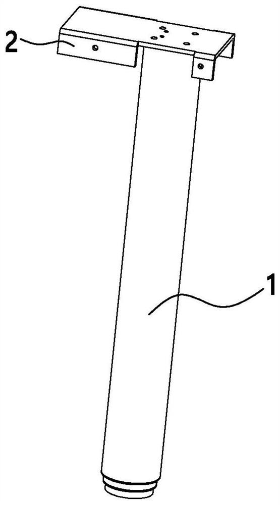
[0031] like Figure 1 ~ Figure 4 As shown, an automatic obstacle avoidance column includes a telescopic sleeve 1, a drive motor, a main control unit for controlling the drive motor, and a transmission assembly 8 that drives the telescopic sleeve 1 to expand and contract under the drive of the drive motor, and the end of the telescopic sleeve 1 A positioning plate 101 is provided. Strain gauges are installed on the outside of the positioning plate 101. The strain gauges are electrically connected to the main control unit. / or fallback instructions.

[0032] In this embodiment, the strain gauges are arranged on the outside of the positioning plate 101. During the actual use of the column, the end of the column will be connected to external hardware such as the installation frame 2 or the feet. 101 is welded on the telescopic sleeve 1, the external firmware and the positioning plate 101 are squeezed against each other, and the strain gauge is installed between the two, which ca...

Embodiment 2

[0040] A lift table includes a table top, and the automatic obstacle avoidance column described in the above embodiment is arranged under the table top.


PUM


Abstract

The invention discloses an automatic obstacle avoidance stand column, which belongs to the technical field of lifting stand columns, and comprises a telescopic sleeve, a driving motor, a main controlunit for controlling the driving motor and a transmission assembly for driving the telescopic sleeve to stretch out and draw back under the driving of the driving motor, a positioning plate is arranged at the end of the telescopic sleeve, a strain gauge is installed on the outer side of the positioning plate, the strain gauge is electrically connected with the main control unit, when the stand column encounters resistance in the ascending process, the main control unit sends out a braking and / or returning instruction according to a level change signal generated when the strain gauges deform, the strain gauges in the stand column are arranged on the outer side of the positioning plate, are close to the motor and do not make contact with the motor, and therefore pressure brought by obstaclescan be sensitively sensed, and false alarm caused by vibration when the motor rotates is reduced, and the sensitivity and the accuracy are improved.

Description

【Technical field】 [0001] The invention relates to the technical field of lifting columns, in particular to an automatic obstacle avoidance column. 【Background technique】 [0002] With the development of economy and technology, intelligent home and office have become the mainstream trend, such as electric lifting table, electric lifting bed, etc., whose lifting is mainly realized by electric lifting column. When the lifting furniture encounters obstacles during the lifting process , if it is not stopped in time, it may damage the obstacle or the structure of the furniture itself. In severe cases, it may collide or squeeze the human body, causing personal injury. The function of stop or fallback is very important. Although some lifting columns on the market also have the function of fallback when encountering resistance, some of them have imperfect performance, low sensitivity and accuracy, and false alarms occur, or the structure Complicated and costly. 【Content of inventi...

Claims


Application Information

Patent Timeline
Patent Type & Authority Applications(China)
IPC IPC(8): H02K11/20H02K11/33H02K7/10A47B13/02A47B9/00A47C19/02
CPCA47B9/00A47B13/02A47C19/02H02K7/10H02K11/20H02K11/33
Inventor 岑余杰张东行郑扬
Owner NINGBO HAISHIKAI DRIVER TECH CO LTD
Learn More