Power environment monitoring device for machine room
A technology for power environment monitoring and computer room, which is applied to the parts and electrical components of TVs and color TVs. fouling effect
- Summary
- Abstract
- Description
- Claims
- Application Information
AI Technical Summary
Problems solved by technology
Method used
Image

Examples
Embodiment
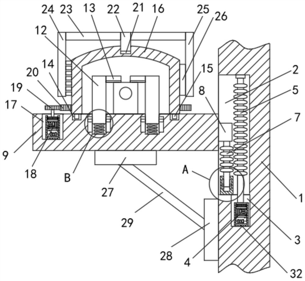
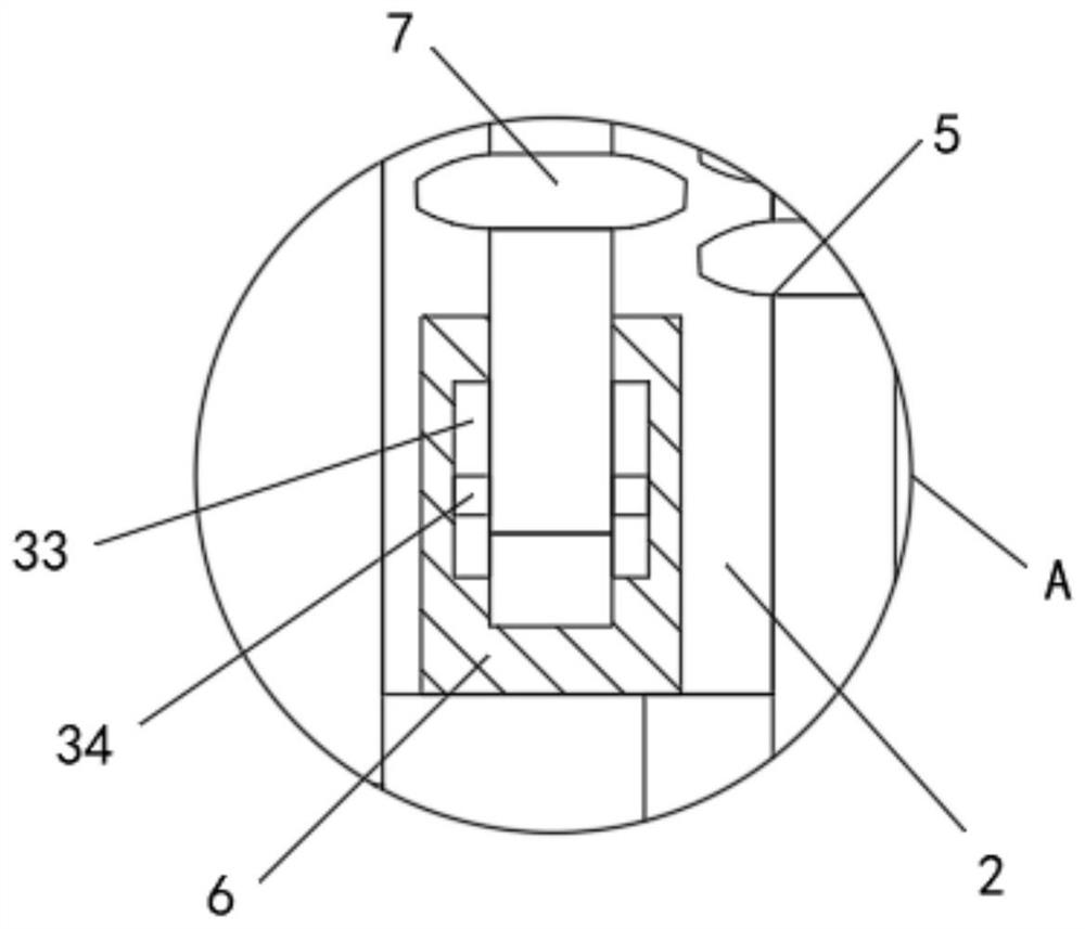
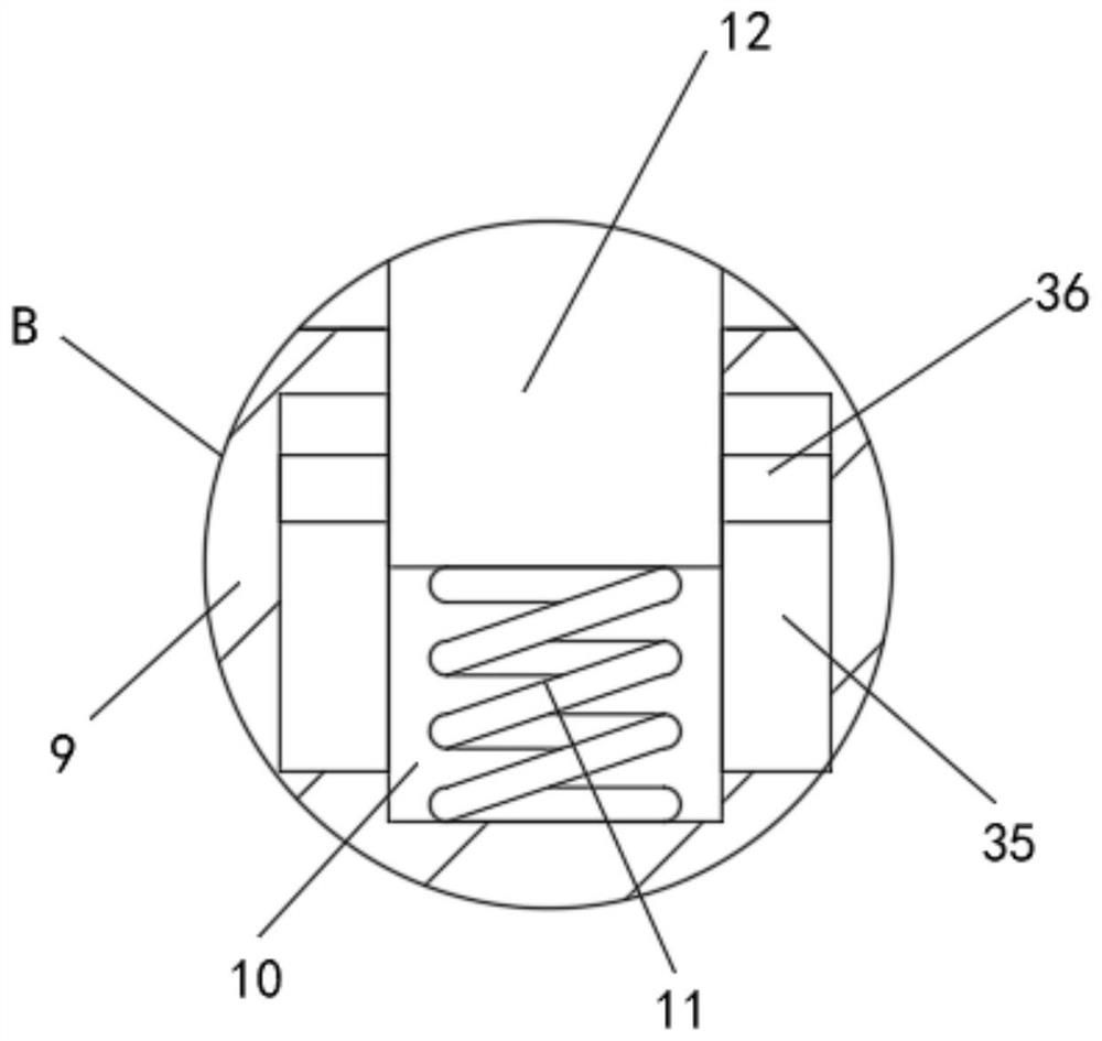
[0026] see Figure 1-4 , the present invention provides a technical solution: a power environment monitoring device for a machine room, including a wall 1, a first groove 2 is opened on one side of the wall 1, and a second groove 2 is opened on the inner bottom wall of the first groove 2. Groove 3, the inner wall of the second groove 3 is screwed with the first motor 4, the output shaft of the first motor 4 is fixedly connected with the first worm 5, the first worm 5 is connected to the first groove 2 by bearing rotation Inside, the inner bottom wall of the first groove 2 is threaded with a sleeve 6, the inner side wall of the sleeve 6 is slidably connected with a second worm 7, the outer side wall of the first worm 5 and the outer side wall of the second worm 7 mesh with each other, The top of the second worm 7 is welded with a connecting block 8, the outer wall of the connecting block 8 is slidably connected to the inside of the first groove 2, and the side of the connecting...
PUM
 Abstract
Description
Claims
Application Information
 - Generate Ideas
- Intellectual Property
- Life Sciences
- Materials
- Tech Scout
- Unparalleled Data Quality
- Higher Quality Content
- 60% Fewer Hallucinations
Browse by: Latest US Patents, China's latest patents, Technical Efficacy Thesaurus, Application Domain, Technology Topic, Popular Technical Reports.
© 2025 PatSnap. All rights reserved.Legal|Privacy policy|Modern Slavery Act Transparency Statement|Sitemap|About US| Contact US: help@patsnap.com