A Floating Boring Tool Arbor for Deep Holes

A boring tool and deep hole technology, which is applied in the field of floating boring tool bar for deep holes, can solve the problems of unfavorable processing, boring tool stuck and broken, mutual friction, etc., and achieve the effect of improving work stability

Active Publication Date: 2021-08-27
SHANDONG UNIV OF SCI & TECH
View PDF5 Cites 0 Cited by
  • Summary
  • Abstract
  • Description
  • Claims
  • Application Information

AI Technical Summary

Problems solved by technology

[0003] At present, most of the boring tools are fixed directly by the tool bar bolts. In the actual use process, due to the accumulation of a large amount of coolant and debris inside the deep hole, it is easy to cause the debris to rub against the workpiece, resulting in The precision of the deep hole is not up to standard, and even damage occurs. Secondly, in the process of processing, different materials need to use different feed amounts. Once the feed amount is too large, it is very likely that the boring tool will be stuck and stuck due to overheating. The problem of breaking, which in turn causes the problem of stuffy turning on the lathe, which is not conducive to stable processing

Method used


Image

  • A Floating Boring Tool Arbor for Deep Holes
  • A Floating Boring Tool Arbor for Deep Holes
  • A Floating Boring Tool Arbor for Deep Holes

Examples


Embodiment 1

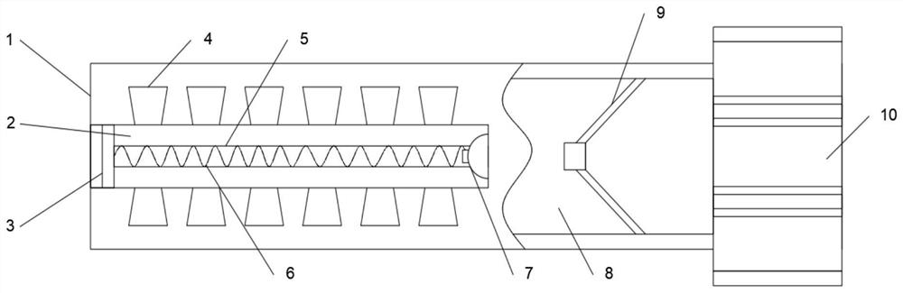
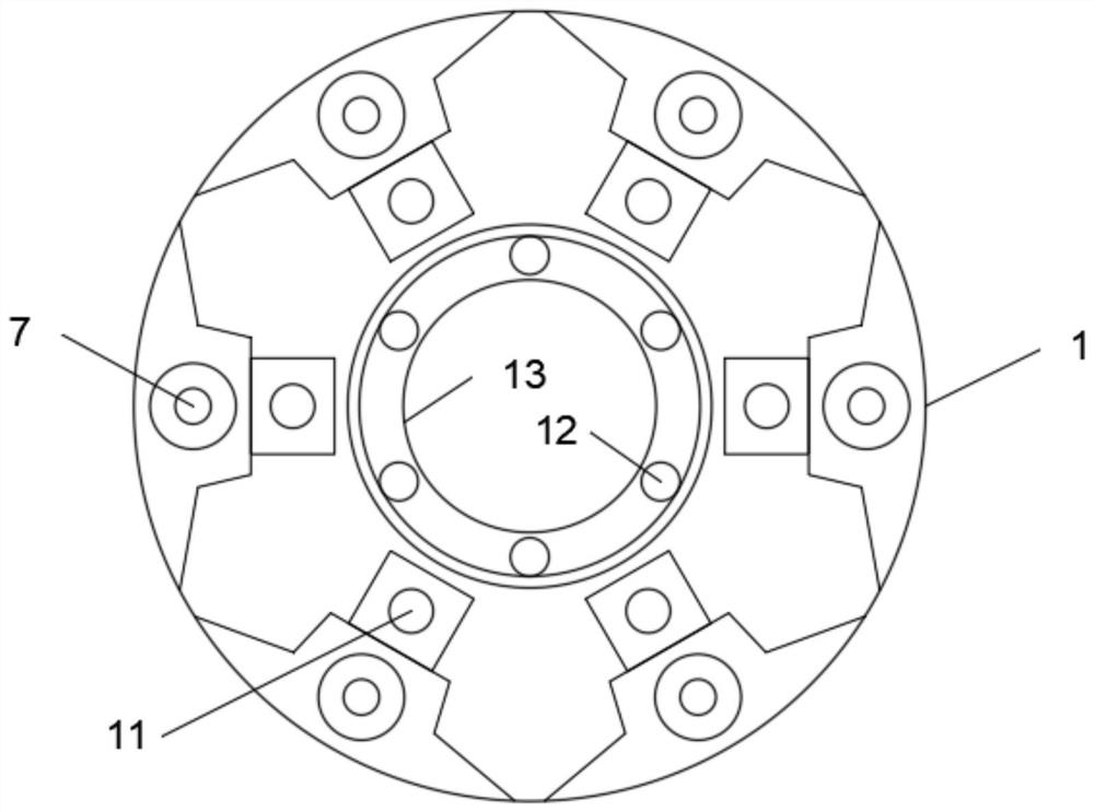
[0025] Embodiment one, with reference to Figure 1 to Figure 6 : A floating boring bar for deep holes, including a tool holder 1, the outer wall of the tool holder 1 is provided with six discharge grooves 2 along the circumferential surface, and the inner walls of the six discharge grooves 2 are all slidingly embedded with scrapers 3 , through the scraper 3, it is possible to quickly discharge debris and waste water. The inner side of the knife seat 1 is provided with six reset chute 5, and the tops of the six reset chute 5 are connected to the bottom of the discharge groove 2 At the end axis, and the center of both sides of the inner wall of the six reset chute 5 is fixedly provided with a limit rod 11, and the outer wall of the limit rod 11 is slidingly sleeved with a return spring 6, through the reset chute 5, limit rod 11 and reset The spring 6 can realize the stable driving and reset of the scraper 3, avoid being stuck on the inner side of the discharge groove 2, and impr...

Embodiment 2

[0026] Embodiment two, refer to Figure 1 to Figure 6 : the outer wall of the knife seat 1 is provided with six groups of auxiliary grooves 4, and one side of the six groups of auxiliary grooves 4 is connected to one side of the discharge groove 2, and one side of the inner wall of the pressure groove 8 is embedded with a pressure cylinder 9, and One end of the pressurized cylinder 9 is communicated with a dredging pipe 21. Through the dredged pipe 21, a stable supply of cooling medium can be realized, and the other end of the pressurized cylinder 9 is communicated with an external cooling liquid supply device. The top of the dredged pipe 21 A limiting tube 20 is communicated, and one side of the outer wall of the limiting tube 20 is embedded in the inner side of the pressure groove 8, and the top of the limiting tube 20 is communicated with six supply tubes 22, through which the nozzle can be cleaned stably The cleaning liquid pressure of 7 is to ensure that the cooling liqui...

Embodiment 3

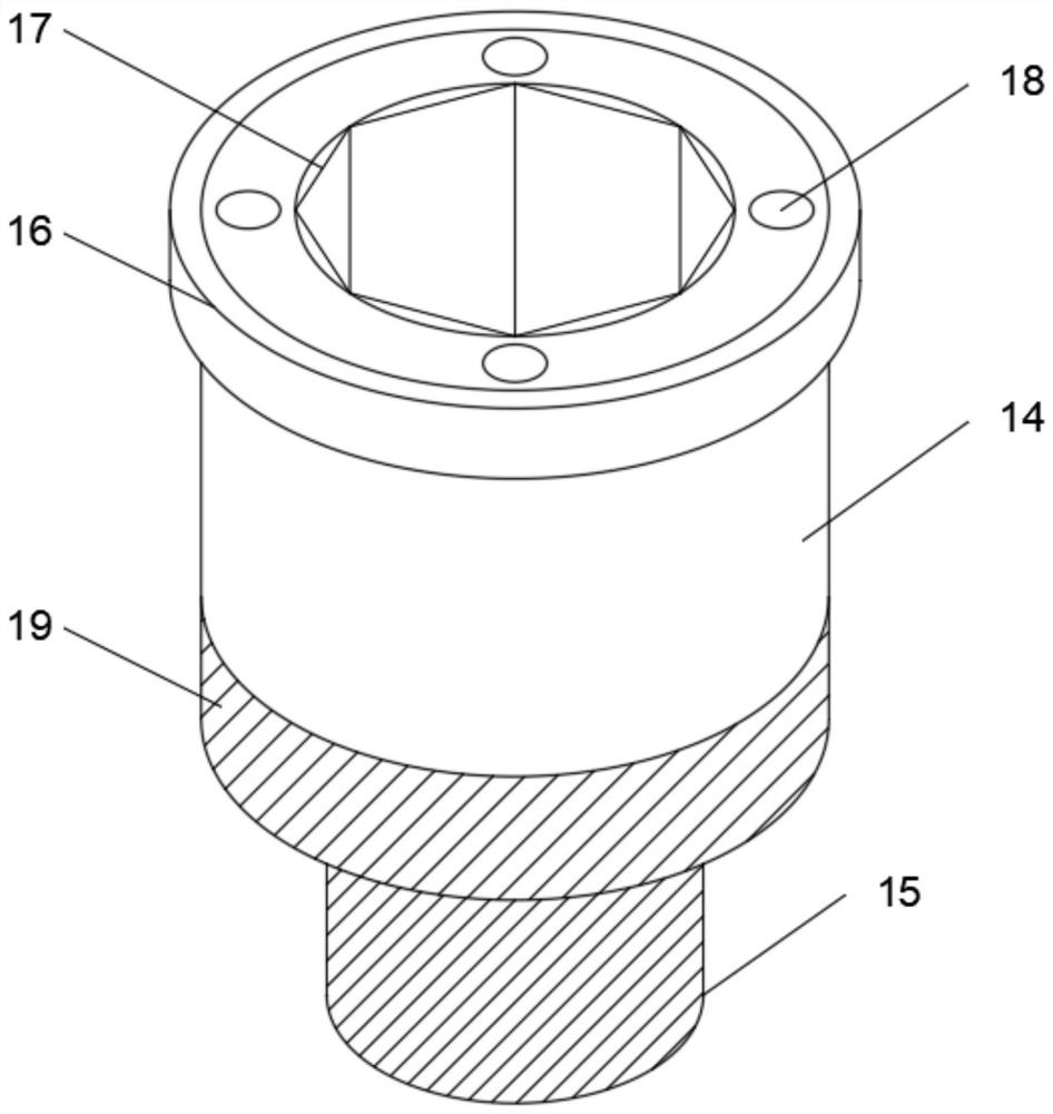
[0027] Embodiment three, refer to Figure 1 to Figure 6 : the top of the installation rod 14 is provided with a plurality of cooling nozzles 18, the inner wall of the installation groove 13 is provided with a plurality of branch holes 12, and one end of the plurality of branch holes 12 is connected to the restricting tube 20, through the branch holes 12 and the cooling nozzle 18 , can realize stable cooling spray on the boring tool, and the other end of a plurality of tributary holes 12 is connected to one end of the cooling nozzle 18, and the top edge of the outer wall of the installation rod 14 is sleeved with a gasket 16, and the gasket 16 is matched with the installation groove 13, and the end of the knife holder 1 away from the scraper 3 is provided with a fixed base 10, and the edge of the outer wall of the fixed base 10 protrudes outward, and the outer wall of the installation rod 14 is provided with an external thread 19, and the installation The bottom end of the rod ...


PUM


Abstract

The invention discloses a floating boring tool bar for deep holes, which includes a tool seat, six discharge grooves are opened on the outer wall of the tool seat along the circumferential surface, and scrapers are slidingly embedded in the inner walls of the six discharge grooves. The inner side of the seat is provided with six reset chutes, and the tops of the six reset chutes are connected to the bottom axis of the discharge groove, and the centers of both sides of the inner walls of the six reset chutes are fixedly provided with limiting rods to limit The outer walls of the rods are all slidingly sleeved with return springs. By cleaning the nozzle, scraper, return spring and discharge groove, rapid discharge of waste water and debris can be achieved to avoid clogging of deep holes with waste water and debris, resulting in substandard precision of workpieces and even jamming of boring tools , through the anti-friction sleeve, cooling nozzle, and installation rod, the temperature of the boring tool can be cooled from time to time, avoiding the problem of boring tool breaking due to excessive tool feed, and further improving the working stability of the boring tool.

Description

technical field [0001] The invention belongs to the technical field of boring cutters, in particular to a floating boring cutter holder for deep holes. Background technique [0002] Boring tool is a kind of boring tool, generally with round handle, and there are also square tool bars for larger workpieces. The most commonly used occasions are boring tool inner hole processing, reaming, profiling, etc., with one or two cutting parts , A tool specially used for roughing, semi-finishing or finishing the existing holes, the boring tool can be used on a boring machine, lathe or milling machine. [0003] At present, most of the boring tools are fixed directly by the tool bar bolts. In the actual use process, due to the accumulation of a large amount of coolant and debris inside the deep hole, it is easy to cause the debris to rub against the workpiece, resulting in The precision of the deep hole is not up to standard, and even damage occurs. Secondly, in the process of processing...

Claims


Application Information

Patent Timeline
Patent Type & Authority Patents(China)
IPC IPC(8): B23B29/02B23Q11/10B23Q11/00
CPCB23B29/02B23Q11/0042B23Q11/10
Inventor 马静敏许建锋沈友徽高洁
Owner SHANDONG UNIV OF SCI & TECH
Why Eureka
Try Eureka