A transition belt cutting machine

A transition belt and cutting machine technology, applied in metal processing equipment, welding equipment, manufacturing tools, etc., can solve the problems of irregularity, difference, low test Reynolds number, etc., and achieve the effect of convenient layout and maintaining smoothness and stability.

Active Publication Date: 2022-04-19
INST OF HIGH SPEED AERODYNAMICS OF CHINA AERODYNAMICS RES & DEV CENT
View PDF0 Cites 0 Cited by
  • Summary
  • Abstract
  • Description
  • Claims
  • Application Information

AI Technical Summary

Problems solved by technology

In the wind tunnel test, due to the relatively low Reynolds number of the test, there is a rather long section of laminar boundary layer on the surface of the model, which causes a large difference between the state of the boundary layer on the surface of the model and the real aircraft.
This difference complicates and irregularizes the influence of Reynolds number in wind tunnel tests

Method used


Image

  • A transition belt cutting machine
  • A transition belt cutting machine
  • A transition belt cutting machine

Examples


Embodiment

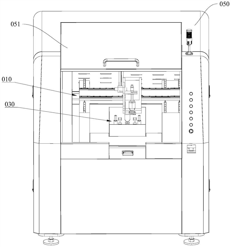
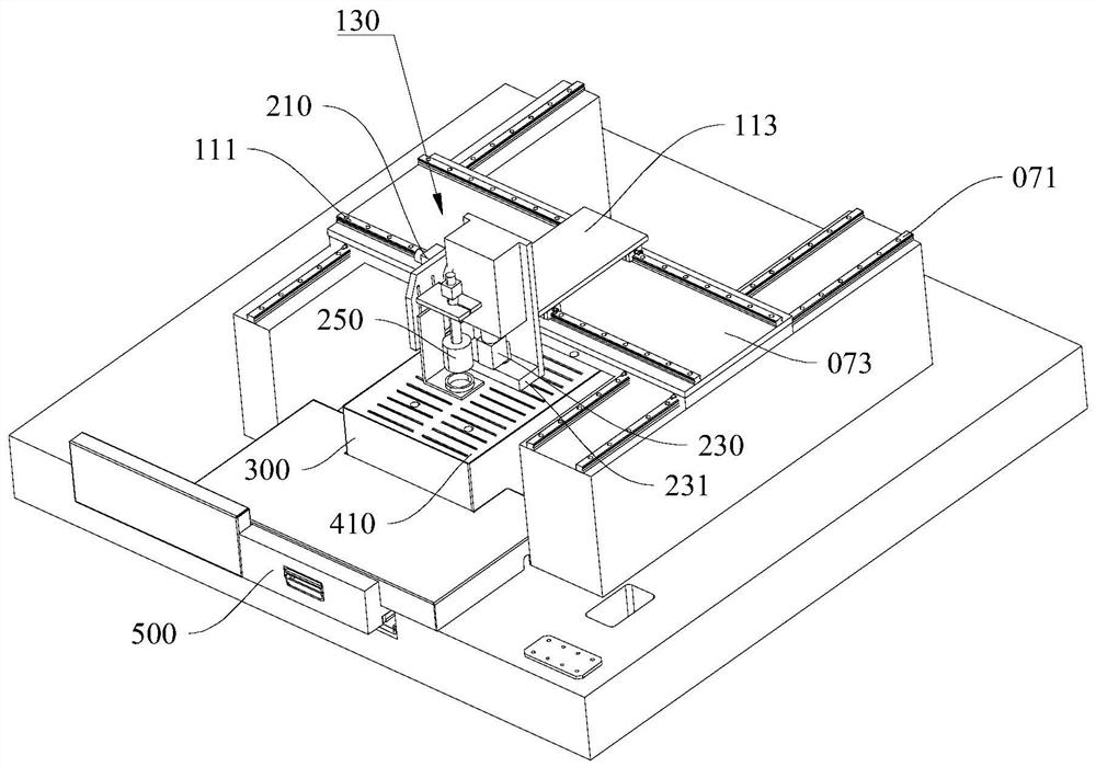
[0057] This embodiment provides a transition zone cutting machine, please refer to figure 1 with figure 2 , including a machine body 050, a transition zone cutting laser emission alignment device 010 and a transition zone cutting carrying device 030;

[0058] The transition belt cutting laser emission alignment device 010 and the transition belt cutting carrier device 030 are installed in the machine body 050, wherein the transition belt cutting carrier device 030 is used to carry the transition belt to be cut, and place the transition belt to be cut stably , and the placement and removal of the transition belt to be cut is realized through the lifting mechanism, and the transition belt cutting laser emission alignment device 010 is used to emit laser light to align the transition belt to be cut on the transition belt cutting carrier device 030 .

[0059] The body 050 is also provided with a flip cover 051 that can be opened and closed. When the flip cover 051 is closed, the...


PUM


Abstract

The invention provides a transition belt cutting machine, which includes a machine body, a transition belt cutting laser emission alignment device and a transition belt cutting bearing device; a transition belt cutting laser emission alignment device and a transition belt cutting bearing device Installed in the body; the transition belt cutting laser emission alignment device and the transition belt cutting bearing device are installed in the body, wherein the transition belt cutting bearing device is used to carry the transition belt to be cut, and stabilize the transition belt to be cut Placement, and the placement and removal of the transition belt to be cut is realized through the lifting mechanism. The transition belt cutting laser emission alignment device is used to emit laser light to align the transition belt to be cut on the transition belt cutting carrier device.

Description

technical field [0001] The invention relates to the field of transition belt production, in particular to a transition belt cutting machine. Background technique [0002] When a real aircraft is flying in the air, due to the high flying Reynolds number, the boundary layer on the surface of each part of the aircraft is almost all in a turbulent state. In the wind tunnel test, due to the relatively low test Reynolds number, there is a rather long section of laminar boundary layer on the surface of the model, which causes a large difference between the state of the boundary layer on the model surface and the real aircraft. This difference complicates and irregularizes the influence of Reynolds number in wind tunnel tests. If the method of artificially fixing the transition of the boundary layer is adopted during the model test, so that the boundary layer on the surface of the model is similar to that of an airplane, the correction of the influence of Reynolds number can be gre...

Claims


Application Information

Patent Timeline
Patent Type & Authority Patents(China)
IPC IPC(8): B23K26/38B23K26/70B23K26/064
CPCB23K26/38B23K26/702B23K26/0643B23K26/064
Inventor 何彬华刘大伟张仁鉴周岭陈植吴继飞李聪健郭秋亭李阳何登熊贵天谢翔吴灿王慧颖
Owner INST OF HIGH SPEED AERODYNAMICS OF CHINA AERODYNAMICS RES & DEV CENT
Why Eureka
Try Eureka