
Mechanical sensing type edge finder

A sensor type and edge finder technology, which is applied in metal processing machinery parts, measuring/indicating equipment, metal processing equipment, etc., can solve the problems of low detection accuracy, difficult operation, and change of detection accuracy, and achieve high detection accuracy , avoid the effect of large precision error and wide application range

Inactive Publication Date: 2021-02-02
张彬
View PDF7 Cites 1 Cited by
  • Summary
  • Abstract
  • Description
  • Claims
  • Application Information

AI Technical Summary

Problems solved by technology

[0005] The invention provides a mechanical sensor type edge finder, which has high detection accuracy, simple operation, does not affect the detection accuracy of the bias type edge finder due to the subjective judgment of the operator, and is suitable for the material of the workpiece to be processed. The advantage of no requirement limit solves the problem that the structure of the offset edge finder is simple, but its detection accuracy will change due to the user's proficiency, and its subjective judgment factors will affect the detection accuracy of the offset edge finder. The larger influence makes its operation more difficult and the detection accuracy is lower. Although the detection accuracy of the photoelectric edge finder is much higher than that of the bias edge finder, and the operation is simple and convenient, but because of its working principle , so that it can only detect conductive materials, but cannot detect non-conductive materials, resulting in a problem that is greatly restricted in the actual use process

Method used


Image

  • Mechanical sensing type edge finder
  • Mechanical sensing type edge finder
  • Mechanical sensing type edge finder

Examples


Embodiment Construction

[0020] The following will clearly and completely describe the technical solutions in the embodiments of the present invention with reference to the accompanying drawings in the embodiments of the present invention. Obviously, the described embodiments are only some, not all, embodiments of the present invention. Based on the embodiments of the present invention, all other embodiments obtained by persons of ordinary skill in the art without making creative efforts belong to the protection scope of the present invention.

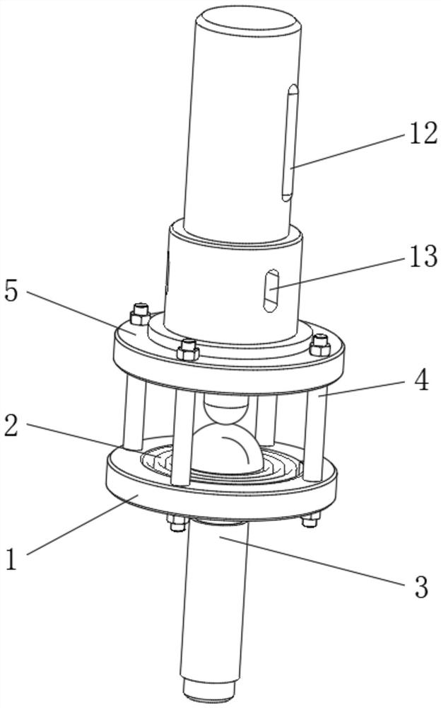
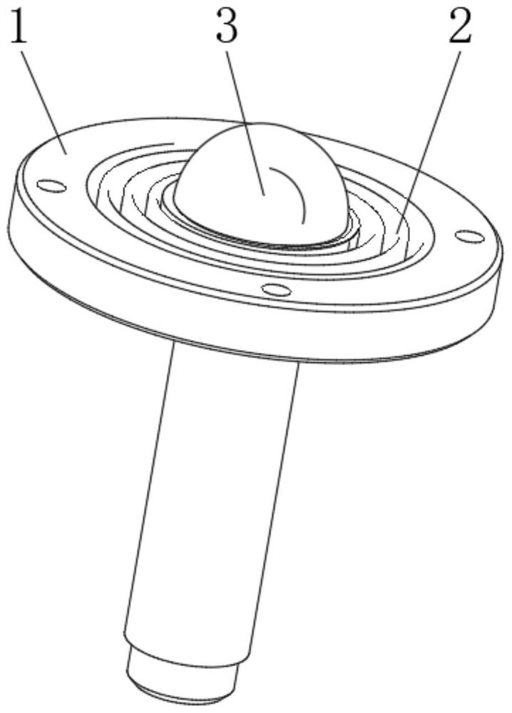
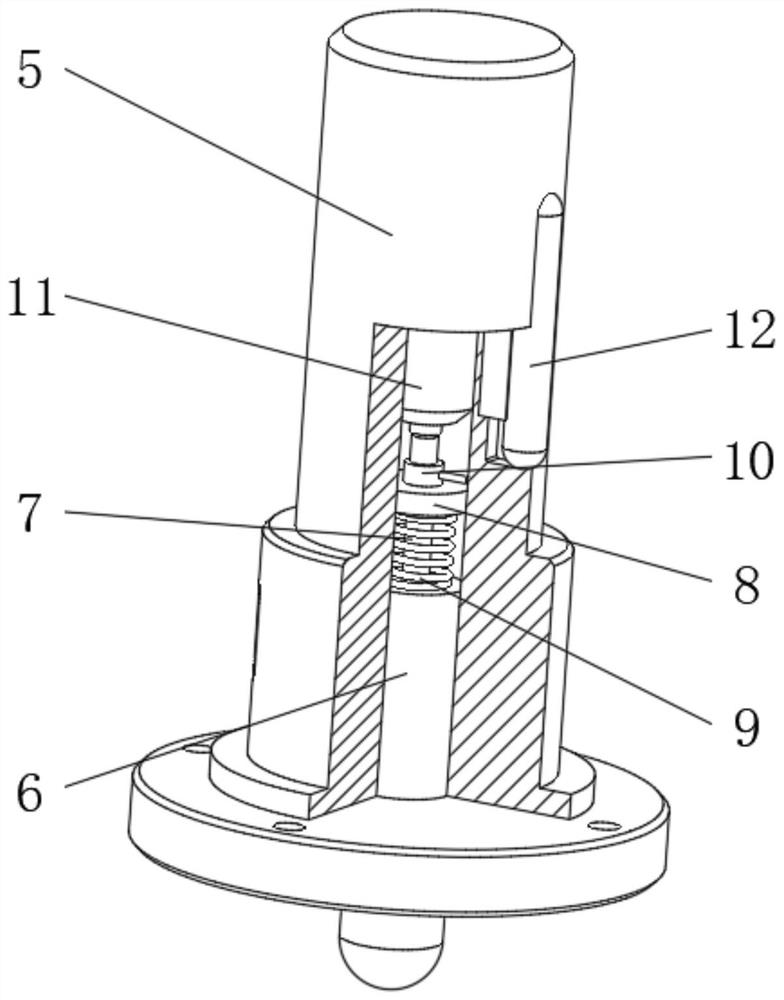
[0021] see Figure 1-3 , a mechanical sensing type edge finder, including a bottom ring 1, a fixed link 4 and a clamping sleeve rod 5, the top of the bottom ring 1 is fixed with a clamping sleeve rod 5 through the fixed link 4, and the bottom is installed The inside of the ring 1 is fixedly installed with a rotary contact rod 3 through a disc spring 2, and the bottom of the inner cavity of the clamping sleeve rod 5 is movably connected with a contact rod 6, an...


PUM


Abstract

The invention relates to the technical field of spindle cutter position detection equipment, and discloses a mechanical sensing type edge finder. The edge finder comprises a mounting bottom ring, a fixed connecting rod and a clamping sleeve rod; the clamping sleeve rod is fixedly mounted at the top of the mounting bottom ring through the fixed connecting rod; a rotary touch rod is fixedly mountedin the mounting bottom ring through a disc spring; a touch connecting rod is movably sleeved with the bottom of an inner cavity of the clamping sleeve rod; and the bottom end of the touch connecting rod makes contact with the top end of the rotary touch rod. According to the mechanical sensing type edge finder, a touch elastic block is arranged to be matched with a conductive connecting rod and apressure spring on the touch connecting rod, two sets of series switches can be formed between a storage battery and a light alarm on the edge finder, the light alarm can be triggered to give an alarmonly when all the switches are turned on, when the edge finder is not clamped and mounted on a machine tool spindle, the touch elastic block is not triggered due to the fact that the touch elastic block is not extruded, and no loss is caused to the current of the storage battery when the edge finder is not use.

Description

technical field [0001] The invention relates to the technical field of spindle tool position detection equipment, in particular to a mechanical sensor type edge finder. Background technique [0002] The edge finder is a detection tool that accurately locates the center position of the workpiece to be processed in CNC machining. By measuring the values ​​​​on both sides of the workpiece to be processed to obtain the average value, the center position of the rotating spindle is obtained, or from the Obtaining the coordinate origin of the part processing program realizes the work of tool setting, alignment and workpiece measurement in NC machining, thereby ensuring the processing accuracy of the part. [0003] The offset edge finder and the photoelectric time edge finder are the two most common edge finders on the market. Among them, the offset edge finder has a simple structure, but its detection accuracy will vary depending on the user's proficiency. However, if changes occu...

Claims


Application Information

Patent Timeline
IPC IPC(8): B23Q17/22
CPCB23Q17/2233
Inventor 张彬
Owner 张彬
Learn More