
Vertical machining center with improved up-down rail

An improved technology for machining centers, applied in metal processing, metal processing equipment, manufacturing tools, etc., can solve the problems of poor transmission efficiency of guide rail slider mechanism, small damping of upper and lower rails, and reduced work efficiency, so as to avoid overshooting Or shock, reduce transmission wear, improve work efficiency

Inactive Publication Date: 2021-02-02
胡美芳
View PDF0 Cites 0 Cited by
  • Summary
  • Abstract
  • Description
  • Claims
  • Application Information

AI Technical Summary

Problems solved by technology

[0004] 1. The lifting stroke of the upper and lower rails is generally long, which not only takes up a lot of space, but also easily causes the transmission efficiency of the guide rail slider mechanism to deteriorate, thereby reducing the work efficiency
[0005] 2. The damping of the upper and lower rails is small and it is easy to cause overshoot or shock, so the protection requirements are higher

Method used


Image

  • Vertical machining center with improved up-down rail
  • Vertical machining center with improved up-down rail
  • Vertical machining center with improved up-down rail

Examples


Embodiment Construction

[0023] The following will clearly and completely describe the technical solutions in the embodiments of the present invention with reference to the accompanying drawings in the embodiments of the present invention. Obviously, the described embodiments are only some of the embodiments of the present invention, not all of them. Based on the embodiments of the present invention, all other embodiments obtained by persons of ordinary skill in the art without making creative efforts belong to the protection scope of the present invention.

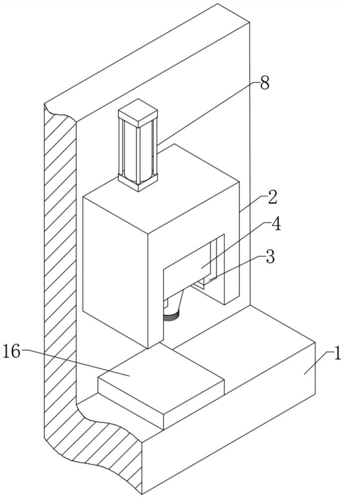
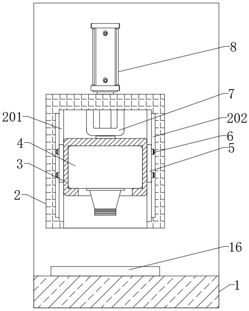
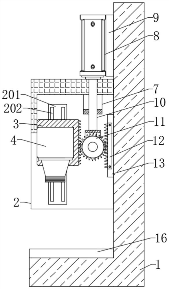
[0024] see Figure 1 to Figure 4 , the present invention provides a technical solution: a vertical machining center with improved upper and lower rails, including an L-shaped base 1, a processing platform 16 is arranged on the L-shaped base 1, and a vertical Type track 2, the vertical track 2 is fixedly installed on the side wall of the base 1, a movable seat 3 is slidably installed in the vertical track 2, and a processing component 4 is fixedly...


PUM


Abstract

The invention relates to the technical field of machining equipment, in particular to a vertical machining center with an improved up-down rail. The vertical machining center comprises an L-shaped base, a machining platform is arranged on the L-shaped base, the vertical rail is arranged over the machining platform, the vertical rail is fixedly installed on a side wall of the base, a movable base is installed in the vertical rail in a sliding mode, a machining assembly is fixedly arranged in the movable base, the movable base is pushed by a speed multiplying device and a driving mechanism to dolinear up-down motion on the vertical rail, the speed multiplying device comprises a hinge base, a spur gear and a rack, the spur gear is rotationally installed on the hinge base through a pin shaft,the driving mechanism comprises a guide plate and a hydraulic cylinder, a piston rod of the hydraulic cylinder penetrates through the guide plate and is fixedly connected with the hinge base, and theguide plate is fixedly arranged on the top wall of the vertical rail. According to the vertical machining center, the stroke of an original hydraulic cylinder can be doubled, so that the transmissionefficiency of the rail is enhanced, and the working efficiency of the mechanism is remarkably improved.

Description

technical field [0001] The invention relates to the technical field of machining equipment, in particular to a vertical machining center with improved upper and lower rails. Background technique [0002] The machining center is a highly automated multifunctional CNC machine tool with a tool magazine and an automatic tool changer. The vertical machining center refers to the machining center whose axis of the spindle is perpendicular to the workbench. The vertical machining center is suitable for processing complex parts such as plates, discs, molds and small shells. The vertical machining center can complete the processes of milling, boring, drilling, tapping and thread cutting. [0003] The upper and lower rails are widely used in vertical machining centers because of their high sensitivity, stable movement, low friction resistance, light movement, small wear, and good precision retention. However, the upper and lower tracks still have the following problems in actual use:...

Claims


Application Information

Patent Timeline
Patent Type & Authority Applications(China)
IPC IPC(8): B23Q37/00
CPCB23Q37/00
Inventor 不公告发明人
Owner 胡美芳
Learn More