Dead zone locking device and side guard plate locking system comprising dead zone locking device

A technology for locking devices and side guards, applied in transportation and packaging, railway car body parts, railway car bodies, etc., can solve problems such as inconvenient operation, waste of manpower and time, and low efficiency, and save manpower and time , improve work efficiency, simple structure effect

Pending Publication Date: 2021-02-02
QINGDAO HONGDA QINGTIAN TRANSPORTATION EQUIP
View PDF0 Cites 0 Cited by
  • Summary
  • Abstract
  • Description
  • Claims
  • Application Information

AI Technical Summary

Problems solved by technology

[0003] One of the existing locking systems needs to be opened with a key, and the other is a movable latch, both of which have parts separate from the locking system. Because the operation process is located on the outside of the side guard, the internal locking structure cannot be seen, which is inconvenient. The installation and disassembly of the side guard is very inconvenient to operate, wastes manpower and time, and is inefficient

Method used


Image

  • Dead zone locking device and side guard plate locking system comprising dead zone locking device
  • Dead zone locking device and side guard plate locking system comprising dead zone locking device
  • Dead zone locking device and side guard plate locking system comprising dead zone locking device

Examples


Embodiment Construction

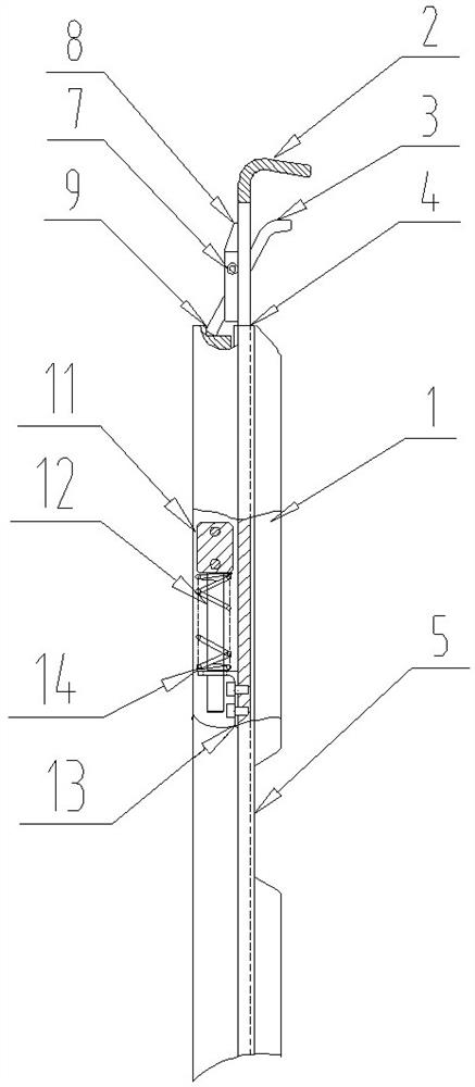
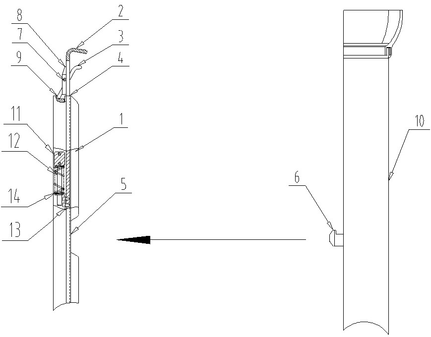
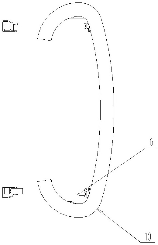
[0024] Combine below Figure 1 to Figure 5 A blind spot locking device and a side guard locking system including the blind spot locking device according to the present invention are described in detail.

[0025] Such as figure 1 As shown, the blind spot locking device of the present invention includes a frame body 1 , a locking plate 2 , a support column 3 , and a positioning shaft 7 .

[0026] The frame body 1 is provided with a chute 4 along the height direction, and the lower part of the lock plate 2 is placed in the chute 4 and can slide along the chute 4 .

[0027] A locking opening 5 is provided on the locking plate 2; the corresponding frame body 1 is also provided with a locking opening there.

[0028] In the middle of the lock plate 2, there is a lock plate through groove capable of accommodating the support column 3, and the support column 3 can rotate in the lock plate through groove.

[0029] The same side of the top of the lock plate 2 and the support column 3 ...


PUM


Abstract

In order to solve the problems of inconvenience in operation and low efficiency due to the fact that an internal structure cannot be seen when an operation side guard plate is mounted, the invention provides a dead zone locking device which comprises a frame body, a lock plate, a support column and a positioning shaft; the frame body is provided with a sliding groove in the height direction, and the lock plate is inserted into the sliding groove from the lower end of the frame body and can slide along the sliding groove; both the lock plate and the frame body are provided with lock openings; alock plate through groove capable of containing the support column is formed in the middle of the lock plate in the width direction. The positioning shaft is fixed in the width direction of the lockplate, the support column sleeves the positioning shaft and can rotate around the positioning shaft in the lock plate through groove, and the gravity center of the support column is below the positioning shaft; handles are arranged on the same sides of the top ends of the lock plate and the support column and a same-hand touchable distance is kept between the two handles; a clamping groove is formed in the top end of the frame body, located on the side opposite to the handle, of the lock plate and located below the support column, and the bottom end of the rotated support column can be clampedand positioned. The invention is simple in structure and convenient to mount and dismount in a dead zone and working efficiency is improved.

Description

technical field [0001] The invention relates to a locking device of a rail vehicle, in particular to a locking system of a windshield side guard of a rail vehicle. Background technique [0002] The rail vehicle is connected with a windshield between two adjacent carriages to form a passage for passengers to pass through and to realize the sealing of the car body. There are side guards on both sides of the passage for protection and decoration. The side guard is installed on the car body, and it needs to be conveniently connected and separated from the car body. Usually, the locking and opening of the side guard is realized through a locking system. However, the height of the side guard is usually more than 1.9 meters, and the locking system is hidden inside the side guard. The operator is always located outside the side guard, which is a blind area of ​​operation and cannot see the locking system. The locking structure is required to be reliable. It is also easy to operate...

Claims


Application Information

Patent Timeline
Patent Type & Authority Applications(China)
IPC IPC(8): B61D17/22
CPCB61D17/22
Inventor 杨勇石静王大伟汪明
Owner QINGDAO HONGDA QINGTIAN TRANSPORTATION EQUIP
Why Eureka
Try Eureka