Eureka AIR delivers breakthrough ideas for toughest innovation challenges, trusted by R&D personnel around the world.

Broadband notch conical beam antenna

A cone beam and notch technology, applied in the direction of antenna, antenna coupling, antenna grounding device, etc., can solve the problems of low received signal strength of omnidirectional probe antenna, reduced measurement accuracy and efficiency, etc., to solve the problem of communication signal and antenna interaction. interference, improve antenna impedance matching, and expand the effect of bandwidth

Pending Publication Date: 2021-02-02
三万星空(西安)信息技术有限公司
View PDF0 Cites 3 Cited by
  • Summary
  • Abstract
  • Description
  • Claims
  • Application Information

AI Technical Summary

Problems solved by technology

[0004] However, when the drone is flying in a circle, the probe antenna has a certain inclination angle relative to the antenna to be measured on the ground, and the gain of the omnidirectional probe antenna decreases in the direction of the inclination angle, which leads to the problem of low received signal strength and the problem of avoiding signal mutual interference, making the measurement system easy. Affected by multi-rotor UAV communication signals, flight attitude and other factors, the measurement accuracy and efficiency are reduced

Method used


Image

  • Broadband notch conical beam antenna
  • Broadband notch conical beam antenna
  • Broadband notch conical beam antenna

Examples


Embodiment 1

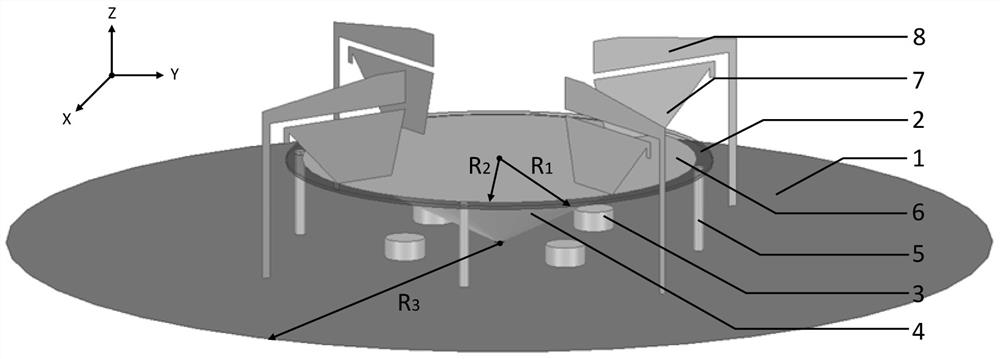
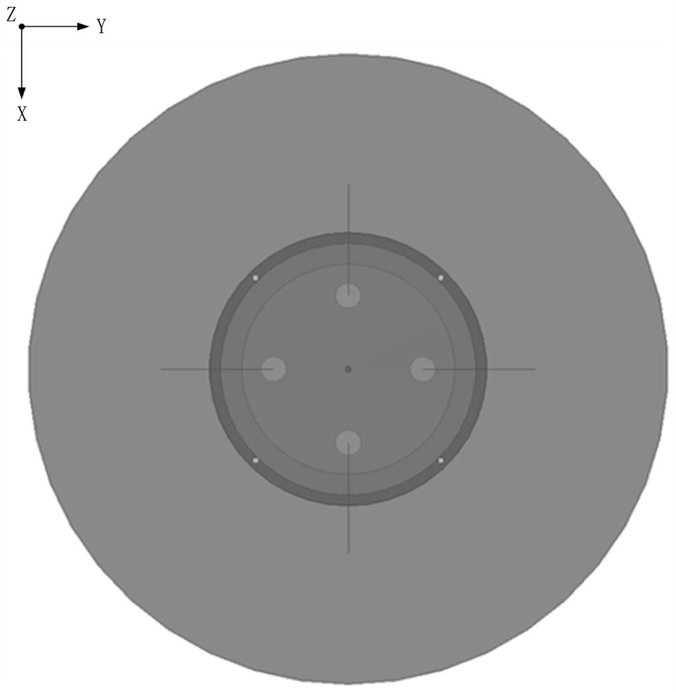
[0040] Example 1: Reference Figure 1~3 As shown, a wide-band notch cone beam antenna includes a circular metal floor 1, a circular dielectric substrate 2 and a metal cone 4, the metal cone 4 is placed upside down on the center of the circular metal floor 1, and the metal cone 4 The top plane of the circular dielectric substrate 2 is connected to the lower surface of the circular dielectric substrate 2, and the circular radiation patch 6 is printed on the upper surface of the circular dielectric substrate 2. The circular radiation patch 6 is connected to the circular metal floor 1 through four short-circuit cylinders 5. connection, four load patches 7 are evenly arranged on the surface of the circular radiation patch 6, and each load patch 7 is provided with a coupling patch 8 corresponding to it one by one and coupled with each other, and each coupling patch 8 is connected to Circular metal floor 1 connection.

[0041]The coupling patch 8 of this embodiment is approximately ...

Embodiment 2

[0048] In Embodiment 2, on the basis of Embodiment 1, the coupling patch 8 and the short-circuit cylinder 5 are removed, and other structures and parameters remain unchanged.

Embodiment 3

[0049] In embodiment 3, on the basis of embodiment 1, the metal parasitic cylinder 3 is removed, and other structures and parameters remain unchanged.


PUM


Abstract

The invention discloses a broadband notch conical beam antenna, which comprises a circular metal floor, a circular dielectric substrate and a metal cone, wherein the metal cone is inversely placed inthe center of the circular metal floor, the top end of the metal cone is connected with the lower surface of the circular dielectric substrate, and a circular radiation patch is printed on the upper surface of the circular dielectric substrate; the circular radiation patch is connected with the circular metal floor through four short-circuit cylinders, four load patches are uniformly arranged on the surface of the circular radiation patch, coupling patches which are in one-to-one correspondence with the load patches and are mutually coupled are arranged at the positions of the load patches, and each coupling patch is connected with the circular metal floor. Four metal parasitic cylinders uniformly arranged on the surface of the circular metal floor are also arranged. The antenna is compactin structure and reasonable in design, has the advantages of broadband and miniaturization, can improve the precision of directional diagram measurement of the multi-rotor unmanned aerial vehicle, and avoids mutual interference between working signals of the multi-rotor unmanned aerial vehicle and a probe antenna.

Description

technical field [0001] The invention belongs to the technical field of antennas, and in particular relates to a wide-band notch conical beam antenna, which can be used in a multi-rotor unmanned aerial vehicle platform measurement system. Background technique [0002] With the rapid development of antennas and radio frequency devices, the device has great application prospects in various fields. Therefore, in order to clearly understand the specific performance of radio frequency devices, antenna measurement technology becomes particularly critical. It has always been very important to accurately measure the radiation performance of large fixed antennas or radio devices throughout their life cycle, such as in the development and optimization of the entire antenna system, handover and upgrade of RF systems, etc. However, during the use of large fixed antennas or radio devices, the radiation performance is affected by various factors, such as pollution, aging, damage from stor...

Claims


Application Information

Patent Timeline
Patent Type & Authority Applications(China)
IPC IPC(8): H01Q1/36H01Q1/38H01Q1/48H01Q19/10H01Q1/52
CPCH01Q1/36H01Q1/38H01Q1/48H01Q1/52H01Q19/10
Inventor 李昂杰程通杨大慰
Owner 三万星空(西安)信息技术有限公司
Why Eureka
Eureka Blog
Learn More