Motor cooling member

A technology for cooling components and motors, applied to cooling/ventilation devices, electrical components, electric components, etc., which can solve problems such as increased pressure loss

Pending Publication Date: 2021-02-02
TAIHO INDUSTRIES CO LTD
View PDF11 Cites 0 Cited by
  • Summary
  • Abstract
  • Description
  • Claims
  • Application Information

AI Technical Summary

Problems solved by technology

The pressure loss of this oil increases as it flows through the circumferential oil passage

Method used


Image

  • Motor cooling member
  • Motor cooling member
  • Motor cooling member

Examples


Embodiment Construction

[0030] Hereinafter, the directions indicated by arrow U, arrow D, arrow F, arrow B, arrow L, and arrow R in the figure are respectively defined as an upward direction, a downward direction, a front direction, a rear direction, a left direction, and a right direction for description. .

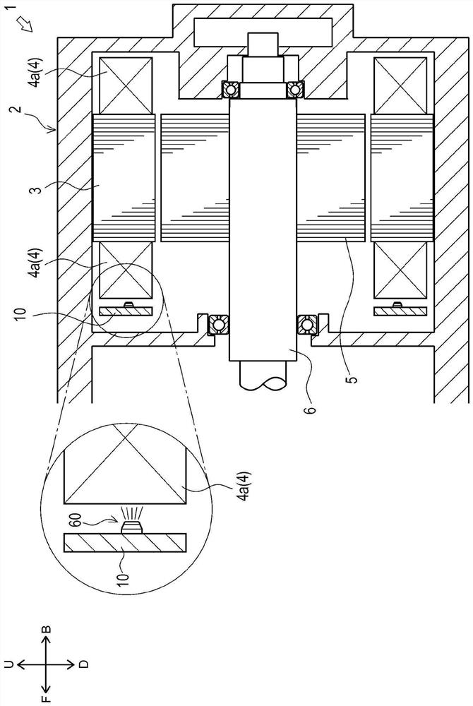
[0031] First, use figure 1 The outline of the structure of the motor 1 provided with the cooling member 10 of 1st Embodiment of this invention is demonstrated.

[0032] The motor 1 of the present embodiment is used in a driving device of an automobile (a hybrid vehicle (HV), an electric vehicle (EV), or the like). The motor 1 mainly has a housing 2 , a stator 3 , a coil 4 , a rotor 5 , a rotating shaft 6 , and a cooling member 10 .

[0033] The case 2 accommodates other components (the stator 3 and the like) constituting the motor 1 . A stator 3 is fixed inside the housing 2 . The stator 3 is formed in a substantially cylindrical shape. The stator 3 is arranged such that its axis faces the...


PUM


Abstract

Provided is a motor cooling member capable of equalizing the amount of oil discharged from a plurality of discharge ports. The motor cooling member is provided with an oil supply port (31) for supplying oil; a plurality of discharge ports (60) that discharge oil toward the motor; a main oil passage (80) connected to the oil supply port (31); and a plurality of derived oil passages (90) formed so as to branch from the main oil passage (80) so as to correspond to the plurality of discharge ports (60), respectively. The plurality of derived oil passages (90) are formed so as to connect the main oil passage (80) and the discharge ports (60), and have different shapes from each other.

Description

technical field [0001] The present invention relates to a technology of a cooling member of a motor capable of supplying oil to the motor for cooling. Background technique [0002] Conventionally, a technique related to a structure in which oil is supplied to a motor for cooling is known. For example, Patent Document 1 describes as follows. [0003] Patent Document 1 describes an oil cooling structure of a motor that cools the coils of the motor by injecting oil toward the coils. Specifically, an annular circumferential oil passage extending along the circumferential direction of the motor is formed on the inner side surface of the housing of the motor described in Patent Document 1. As shown in FIG. In addition, a plurality of injection holes for injecting oil flowing through the circumferential oil passage toward the coil are formed in a member (oil passage cover) covering the circumferential oil passage. In the oil cooling structure described in Patent Document 1, the ...

Claims


Application Information

Patent Timeline
Patent Type & Authority Applications(China)
IPC IPC(8): H02K9/00H02K9/19
CPCH02K9/00H02K9/19
Inventor 野中照美鹿内大辅
Owner TAIHO INDUSTRIES CO LTD
Why Eureka
Try Eureka