Component installation line

A technology for installing lines and components, applied in the direction of electrical components, electrical components, etc., can solve problems such as the inability to improve production efficiency, and achieve the effects of improving production efficiency, achieving equalization, and realizing cycle time

Active Publication Date: 2016-06-29
FUJI KK
View PDF6 Cites 0 Cited by
  • Summary
  • Abstract
  • Description
  • Claims
  • Application Information

AI Technical Summary

Problems solved by technology

However, when the number of mounted components to be mounted on the boards carried in the two board conveying units is significantly different, the loading of the other board cannot be completed until the mounting on the other board is completed, so that the production efficiency cannot be improved.

Method used


Image

  • Component installation line
  • Component installation line
  • Component installation line

Examples


Embodiment 1

[0037] Hereinafter, a first embodiment of a component mounting line in which electronic component mounting devices of a plurality of modules are arranged in-line according to the present invention will be described based on the drawings.

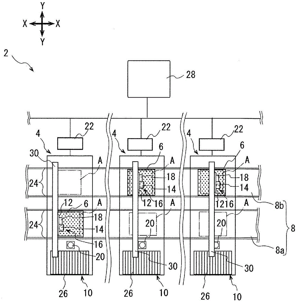
[0038] The component mounting line 2 has electronic component mounting devices 4 as component mounting devices, and a plurality of them are arranged in series (twelve in total).

[0039] Such as figure 1 As shown, the electronic component mounting device 4 includes: a substrate conveying device 8, which carries the substrate 6 into the loading position and locates it at a predetermined component mounting position A; a component supply device 10; a component transfer device 16 with a mounting head 14 and a mark identification The camera 18 is provided on the moving table 12 supported so as to be able to move to the conveying direction of the substrate 6, that is, the X direction and the Y direction horizontally perpendicular to the X directio...

Embodiment 2

[0077] Next, a second embodiment of a component mounting line in which electronic component mounting devices of a plurality of modules according to the present invention are arranged in series will be described below. The configuration of the device used is the same as that of the first embodiment, and thus description thereof will be omitted.

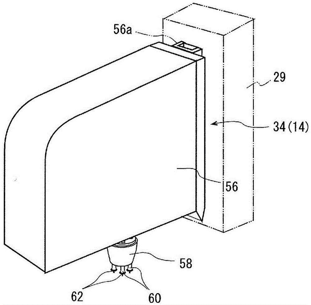
[0078] This embodiment can be carried out continuously with the flow steps of the first embodiment, and can be implemented as a subsequent process of step 111 . In addition, the medium-speed head 34 in this embodiment corresponds to the high-speed head in Claim 3 and Claim 4 with respect to the general-purpose head 36 .

[0079]The control device 22 determines whether or not there is an electronic component mounting device 4 that can be replaced with the medium-speed head 34 among the modules of the electronic component mounting device 4 including the general-purpose head 36 that has not been replaced in the first embodiment ( S201 ). ...


PUM


Abstract

Provided is a component mounting line that enables optimization of production efficiency by using a plurality of modular component mounting devices that are connected in series and that each have two parallel substrate transport devices. In the plurality of modular component mounting devices which are connected in series and each of which has two parallel substrate transport devices, one pair of substrate transport devices positions two mutually different types of substrates at a component mounting position on each component mounting device and transports the substrates to and from the mounting positions, the component mounting devices being provided with the following: a total cycle time computation unit for finding total cycle time by computing for each component mounting device one cycle time for mounting a component onto one of the two types of substrate and another cycle time for mounting a component onto the other of the two types of substrates; and an equal component distribution unit for distributing to every component mounting device the components to be mounted onto the pair of substrates so that the total cycle times are equalized.

Description

technical field [0001] The present invention relates to a component mounting line in which a plurality of component mounting devices including two substrate conveyance units extending in parallel are arranged in series, and a part of the plurality of component mounting devices includes mounting heads with different mounting speeds. Background technique [0002] Conventionally, as equipment for producing substrates on which multiple components are mounted, there are usually solder printers, component mounting devices, reflow ovens, inspection devices, etc., and board transfer devices connect them to form a substrate production line. Furthermore, there are many cases where a component mounting line is configured by arranging a plurality of modularized component mounting apparatuses in-line. In addition, in the component mounting device for mounting components, there are two substrate conveying parts arranged in parallel to each other, and two substrates of the same type or dif...

Claims


Application Information

Patent Timeline
Patent Type & Authority Patents(China)
IPC IPC(8): H05K13/00
CPCH05K13/085
Inventor 安井义博
Owner FUJI KK
Why Eureka
Try Eureka