Eureka AIR delivers breakthrough ideas for toughest innovation challenges, trusted by R&D personnel around the world.

A Broadband Dual Polarization Array Antenna Unit

An array antenna and wide-band technology, applied in the field of new wide-band dual-polarization array antenna units, can solve problems such as complex structures of wide-angle impedance matching layers, achieve dual-polarization feeding, facilitate integration, and have good shielding effects Effect

Active Publication Date: 2022-04-08
BEIJING RES INST OF TELEMETRY +1
View PDF8 Cites 0 Cited by
  • Summary
  • Abstract
  • Description
  • Claims
  • Application Information

AI Technical Summary

Problems solved by technology

The wide-angle impedance matching layer has a complex structure and needs to be loaded at a specific position above the array, which also puts forward higher requirements for the structural design of the phased array

Method used


Image

  • A Broadband Dual Polarization Array Antenna Unit
  • A Broadband Dual Polarization Array Antenna Unit

Examples


Embodiment 1

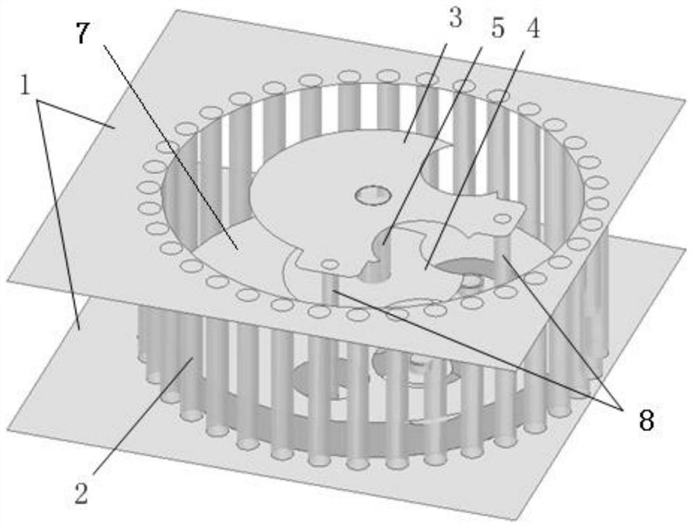
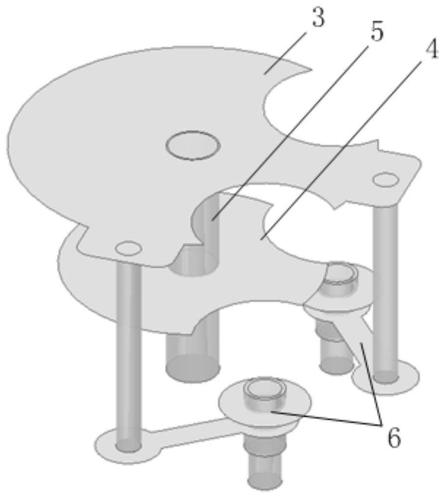
[0024] A new wide-band dual-polarized array antenna unit, including upper and lower floors 1, metalized through holes 2, radiation patches 3, reflective patches 4, central grounding through holes 5, stripline transfer structures 6, and middle floors 7 , SMD feed probe 8;

[0025] The metallized through holes 2 are located between the upper and lower floors 1 and are connected to the upper and lower floors 1. A plurality of metallized through holes 2 are distributed in a circular shape to form a cylindrical area; the radiation patch 3, the reflective patch 4, and the center ground Both the through hole 5 and the stripline transfer structure 6 are located in the cylindrical area;

[0026] The radiation patch 3 is located on the same plane as the first surface of the upper and lower floors 1, and the reflective patch 4, the middle floor 7, and the stripline transition structure 6 are sequentially away from the first surfaces of the upper and lower floors 1;

[0027] The central ...

Embodiment 2

[0032] A new wide-band dual-polarization array antenna unit, the overall technical scheme is as follows: the upper and lower floors 1, metallized through holes 2, radiation patch 3, reflective patch 4, central grounding through hole 5, stripline transfer structure 6. The middle floor is composed of 7 and patch feeding probes 8. The antenna unit is processed based on PCB technology, and the engineering implementation is simple. The upper and lower floors and the metalized through holes together form an electromagnetic shielding structure, which improves the array scanning characteristics without increasing the unit volume, and is suitable for large-angle scanning array antennas with densely arranged units. Combining the radiation and reflection double-layer patch structure increases the bandwidth of the antenna unit and realizes the equalization of the dual polarization pattern of the antenna unit. A grounding hole is added in the middle of the radiation patch of the antenna u...


PUM


Abstract

A new broadband dual-polarization array antenna unit belongs to the field of antenna technology. The top of the antenna unit is grounded through a metallized through hole around the unit boundary, which effectively reduces the fluctuation of the active standing wave ratio of the unit during the array scanning process, which is beneficial to Realize impedance matching under wide scanning angle, improve the beam scanning characteristics of the array antenna unit; use the radiation patch combined with the reflective patch to increase the bandwidth of the antenna unit, and realize the equalization of the E-plane and H-plane radiation patterns; A grounding hole is added in the middle of the radiation patch of the antenna unit, so that the center of the radiation patch becomes a zero potential point, combined with the method of switching the position of the feed point with a strip line, the two port positions required by the dual-polarization antenna unit are realized The flexible selection of is beneficial to the integration of the antenna unit and the TR component.

Description

technical field [0001] The invention relates to a novel broadband dual-polarization array antenna unit, in particular to a novel broadband dual-polarization array antenna unit for a large-angle scanning array antenna system, and belongs to the technical field of antennas. Background technique [0002] Phased array antennas are widely used in many fields such as radar, measurement and control, and communication because of their outstanding advantages such as fast scanning of beam direction, flexible change of beam shape, spatial synthesis of radiated power, and simultaneous multi-beam realization. For an array antenna with a scanning range of ±60°, in order to avoid the appearance of grating lobes, the element spacing is generally about half a wavelength. Smaller unit spacing increases the mutual coupling between adjacent units, which in turn leads to fluctuations in the active input impedance of the units in the array and deterioration of the pattern of the units in the arra...

Claims


Application Information

Patent Timeline
Patent Type & Authority Patents(China)
IPC IPC(8): H01Q1/36H01Q1/48H01Q1/50H01Q1/52H01Q19/10
CPCH01Q1/36H01Q1/50H01Q1/48H01Q19/10H01Q1/526
Inventor 史永康李凉海师亚辉丁克乾魏世京姚家玮
Owner BEIJING RES INST OF TELEMETRY
Why Eureka
Eureka Blog
Learn More