Boot for constant velocity universal joint, and constant velocity universal joint

A technology of constant velocity universal joints and protective covers, which is applied in the direction of elastic couplings, engine seals, engine components, etc., can solve the problems of snake belly depression and difficulty in ensuring the deformation state of protective covers, etc., to improve wear resistance, Excellent durability and compactness

Active Publication Date: 2015-05-20
NTN CORP
View PDF5 Cites 0 Cited by
  • Summary
  • Abstract
  • Description
  • Claims
  • Application Information

AI Technical Summary

Problems solved by technology

However, even with this technology, it is difficult to ensure a stable deformation state of the protective cover
Especially at high angles of action sometimes creates a depression in the snake's belly

Method used


Image

  • Boot for constant velocity universal joint, and constant velocity universal joint
  • Boot for constant velocity universal joint, and constant velocity universal joint
  • Boot for constant velocity universal joint, and constant velocity universal joint

Examples


Embodiment Construction

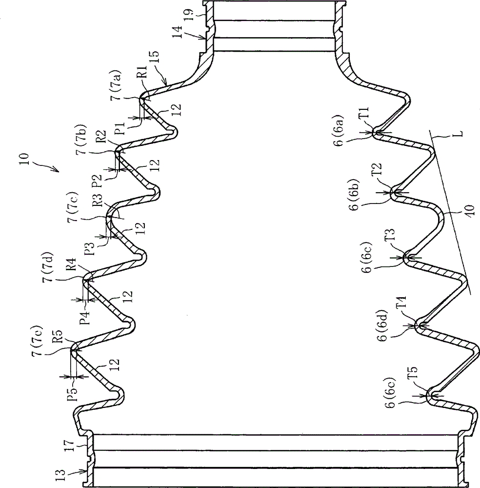
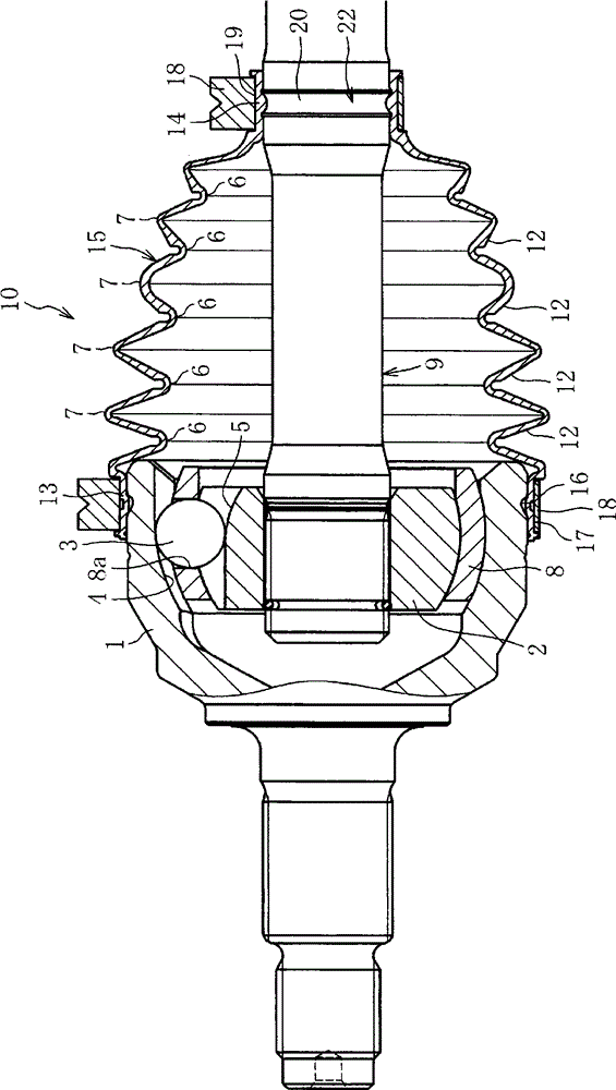
[0034] Below, combine Figure 1 ~ Figure 3 Embodiments of the present invention will be described. figure 1 Indicates the protective cover for constant velocity universal joints according to the present invention, figure 2 Indicates a constant velocity universal joint using a protective cover for a constant velocity universal joint.

[0035] Such as figure 2 As shown, the constant velocity universal joint is composed of the following parts: the outer ring 1 as the outer joint part is formed with a plurality of guide grooves (raceway grooves) 4 in the axial direction on the inner peripheral surface; The inner ring 2 as an inner joint part of the guide groove (raceway groove) 5; a plurality of balls 3 arranged on the ball raceway formed by the cooperation of the guide groove 4 of the outer ring 1 and the guide groove 5 of the inner ring 2; And a spacer 8 (cage) having a pocket 8a for accommodating the ball 3 and the like. In addition, a rotating shaft 9 is connected to th...


PUM


Abstract

A boot has a bellows section that includes three or more peak portions and three or more valley portions. A radially outer portion of each of the peak portions in vertical cross-section of the boot is formed into a round shape. A curvature radius of the radially outer portion of a peak portion being positioned at a central portion between a large diameter section and a small diameter section is set to be larger than curvature radii of the radially outer portions of the other peak portions.

Description

technical field [0001] The present invention relates to boots for a constant velocity universal joint and a constant velocity universal joint. Background technique [0002] In constant velocity universal joints used to transmit power in automobiles and various industrial machines, a bellows-shaped protective cover is installed to prevent foreign matter such as dust from entering the joint and to prevent the grease sealed inside the joint from leaking. [0003] Such as image 3 As shown, this protective cover has: a large-diameter portion 33 fixed to the outer ring of the outer joint member as a constant velocity universal joint, a small-diameter portion 34 fixed to a rotating shaft extending from the inner ring of the inner joint member, The bellows 35 is provided between the large-diameter portion 33 and the small-diameter portion 34 and has valley portions 36 and mountain portions 37 alternately formed therein. Also, the large-diameter portion 33 and the small-diameter po...

Claims


Application Information

Patent Timeline
Patent Type & Authority Patents(China)
IPC IPC(8): F16D3/84F16J3/04F16J15/52
CPCF16D3/845F16J3/043F16D3/223
Inventor 高部真一
Owner NTN CORP
Why Eureka
Try Eureka