Atomizer with central fog suction channel and integrated atomization assembly

An atomization component and an integrated technology, applied in the field of atomizers, can solve the problems of inconvenient automatic production, poor user experience, and inability to seal with glass fiber rope or cotton rope, so as to improve the efficiency of inhaling vapor and mist, and facilitate fully automated production , good liquid storage and fluid conduction performance

Pending Publication Date: 2021-02-05
HUIZHOU HAPPY VAPING TECH LTD
View PDF0 Cites 3 Cited by
  • Summary
  • Abstract
  • Description
  • Claims
  • Application Information

AI Technical Summary

Problems solved by technology

[0004] In the existing electronic atomization equipment, the material used as the conductive liquid in the atomizer is generally a long strip of glass fiber rope or cotton rope, and the heating wire is directly wound on the glass fiber rope or cotton rope. Due to its small size, The liquid storage performance is poor. During the heating process, it is easy to burn due to the small amount of liquid storage and the untimely conduction of the atomized liquid, resulting in burnt smell, resulting in poor user experience.
In addition, in the structure of the atomizer using glass fiber rope or cotton rope as the liquid guide, the glass fiber rope or cotton rope is generally erected horizontally above the atomization seat, and the two ends of the glass fiber rope or cotton rope extend into the liquid storage chamber. Absorb and conduct the atomized liquid. Generally, this structure cannot completely seal the liquid storage chamber and the glass fiber rope or cotton rope. When the user has a large suction force, it is easy to cause liquid leakage.
In addition, in production, it is necessary to wrap the glass fiber rope or cotton rope around the heating wire and install it on the atomizing seat, and then put the atomizing seat and other accessories into the atomizing shell of the atomizer one by one for assembly, the structure is complicated and the assembly is inconvenient , low production efficiency and inconvenient for automated production

Method used


Image

  • Atomizer with central fog suction channel and integrated atomization assembly
  • Atomizer with central fog suction channel and integrated atomization assembly
  • Atomizer with central fog suction channel and integrated atomization assembly

Examples


Embodiment

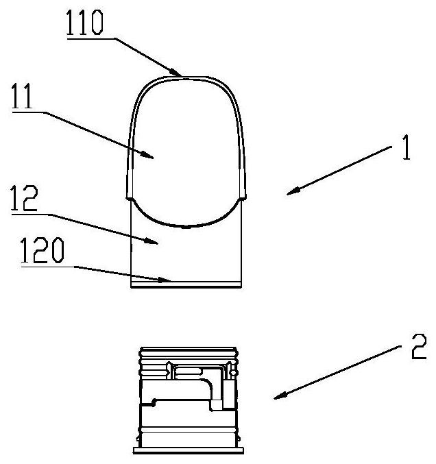
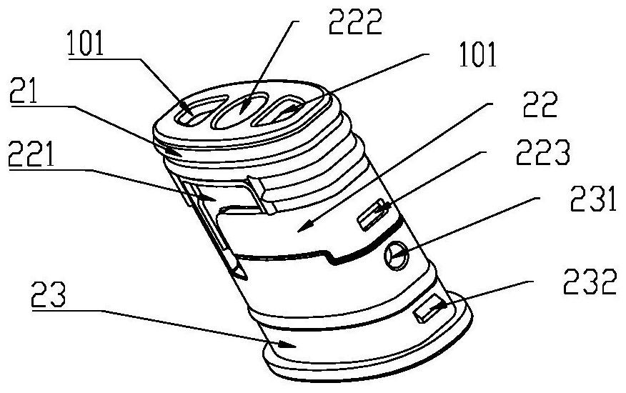
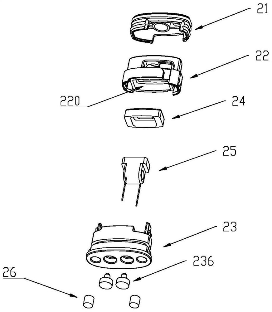
[0045] Such as figure 1 , figure 2 , Figure 9 As shown, an atomizer with a central mist suction channel and an integrated atomization assembly, including an atomization shell 1 and an integrated atomization assembly 2, the atomization shell 1 includes a suction nozzle end 11 and a connecting end 12, the suction nozzle The end 11 is provided with a suction port 110, and the connecting end 12 is provided with an opening 120. The atomizing shell 1 is connected with the battery assembly (not shown in the figure) through the connecting end 12 to form an electronic atomization device. The integrated atomizing component 2 is opened from the atomizing shell. 120 is loaded into the atomization shell 1. The inner walls of both sides of the connecting end 12 of the atomizing shell are provided with first card slots 122, and the side walls of the base 23 are provided with first convex buttons 232 that are buckled with the first card slots 122, and the buckle connection makes the integ...


PUM


Abstract

The invention discloses an atomizer with a central fog suction channel and an integrated atomization assembly. The atomizer comprises an atomization shell, wherein a suction port is formed in the suction nozzle end of the atomization shell, an opening is formed in a connecting end, the atomization shell is connected with a battery assembly through the connecting end to form electronic atomizationequipment, the atomizer further comprises the integrated atomization assembly, and the integrated atomization assembly is arranged in the atomization shell from the opening. The atomization shell extends downwards to be provided with the fog suction channel from the suction port, the fog suction channel is arranged in the center of the atomization shell, the integrated atomization assembly comprises a liquid storage chamber sealing sleeve, an atomization core base and a base which are sequentially connected from top to bottom, and a mounting groove which is concave upwards is formed in the lower end of the atomization core base; and n atomization core sealing sleeve and an upper section of an atomization core are mounted in the mounting groove, a base cavity is downwards formed in the upper end of the base, the lower section of the atomization core extends into a base cavity, and the base blocks an opening of the atomization shell. The atomizer has the advantages of being good in liquid guide effect, even in steam fog generated in the heating atomization process, firm in structure, free of deformation and not prone to liquid and gas leakage.

Description

technical field [0001] The invention relates to the technical field of electronic atomization equipment, and more specifically, the invention relates to an atomizer with a central atomization channel and an integrated atomization assembly. Background technique [0002] Electronic atomization equipment generally includes a battery assembly and an atomizer. The battery assembly is equipped with a battery that supplies power to the atomizer. The atomizer includes a heating unit that can atomize the solution to be atomized into vapor when it is powered on. mist for the user to inhale into the mouth. [0003] Electronic atomization equipment specifically includes medical liquid atomization equipment, etc., and its basic task is to provide a heating process to convert the atomization liquid or liquid medicine stored in the electronic atomization equipment into vapor mist, aerosol, steam, etc. [0004] In the existing electronic atomization equipment, the material used as the cond...

Claims


Application Information

Patent Timeline
Patent Type & Authority Applications(China)
IPC IPC(8): A61M15/06A61M15/00A61M11/00A24F40/48A24F40/485A24F40/42A24F40/10
CPCA61M15/06A61M15/0001A61M11/00A24F40/48A24F40/485A24F40/42A24F40/10
Inventor 林光榕郑贤彬
Owner HUIZHOU HAPPY VAPING TECH LTD
Why Eureka
Try Eureka