Municipal building with high-rise automatic ventilation and temperature regulation structure

An automatic, high-rise technology, applied in the direction of space heating and ventilation control input, buildings, ventilation systems, etc., can solve the problems of low resource utilization, no comfortable air quality, human health impact, etc., to achieve the effect of improving the recycling rate

Active Publication Date: 2021-02-05
林州市海悦兴建筑工程有限公司
View PDF8 Cites 1 Cited by
  • Summary
  • Abstract
  • Description
  • Claims
  • Application Information

AI Technical Summary

Problems solved by technology

Generally, the natural ventilation of traditional buildings is formed by convection, which requires that the orientation of the building must face the wind direction, but the wind direction is changing, and the doors and windows cannot be opened when the wind is strong, and there is no comfortable air quality in the home for a large part of the time. At the same time, due to the increasingly serious air pollution, such as the smog weather caused by PM2.5 pollution in the north, the quality of indoor air in natural ventilation is reduced, which has an impact on human health.
[0003] Existing municipal buildings generally do not have the function of high-rise automatic ventilation, the resource utilization rate is low, and they do not have a certain temperature control function, and they generally use air conditioners to control the indoor air temperature, but there is a large energy consumption, and the room Must be airtight, poor indoor air quality, poor air circulation

Method used


Image

  • Municipal building with high-rise automatic ventilation and temperature regulation structure
  • Municipal building with high-rise automatic ventilation and temperature regulation structure
  • Municipal building with high-rise automatic ventilation and temperature regulation structure

Examples


Embodiment Construction

[0029] The following will clearly and completely describe the technical solutions in the embodiments of the present invention with reference to the accompanying drawings in the embodiments of the present invention. Obviously, the described embodiments are only some, not all, embodiments of the present invention. Based on the embodiments of the present invention, all other embodiments obtained by persons of ordinary skill in the art without making creative efforts belong to the protection scope of the present invention.

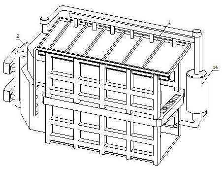
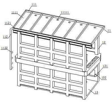
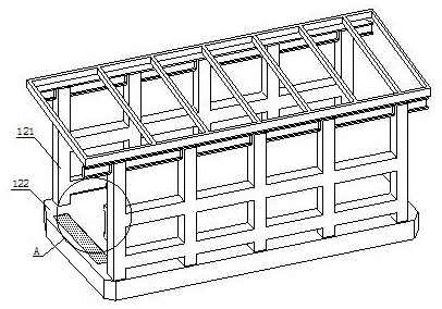
[0030] refer to Figure 1-4 , a municipal building with a high-rise automatic ventilation and temperature control structure, including a building mechanism 1 and an infusion pumping mechanism 2, the infusion pumping mechanism 2 is installed on one side of the building mechanism 1, and the building mechanism 1 includes a slope The roof 11, the upper chamber 12, the lower chamber 13, and the air-cleaning structure 14. The outer surfaces of the sloping roof 11 ar...


PUM


Abstract

The invention discloses a municipal building with a high-rise automatic ventilation and temperature regulation structure. The municipal building comprises a building mechanism and an infusion pumpingmechanism, and the infusion pumping mechanism is installed on the outer wall of one side of the building mechanism. According to the municipal building, air in the upper-layer house cavity and the bottom-layer house cavity can naturally flow under the action of negative pressure by means of air pressure caused by indoor and outdoor wind power or hot pressure caused by indoor and outdoor temperature difference, natural ventilation is formed; turbid air is sucked into a purification barrel through an induced draft fan by means of the transverse air conveying guide pipe, and the harmful impurities in the air are absorbed by the adsorption layer; after purification treatment, the air can be exhausted into the bottom-layer house cavity through an exhaust outlet by means of an exhaust bent guidepipe through an exhaust fan; and meanwhile, a ventilation net is arranged between the upper-layer house cavity and the bottom-layer house cavity, air can rise into the upper-layer house cavity underthe action of air pressure for ventilation, and the air enters the purification barrel through an air inlet insertion pipe again when becoming dirty air, so that ventilation circulation is completed.

Description

technical field [0001] The invention relates to the technical field of municipal buildings, in particular to a municipal building with a high-rise automatic ventilation and temperature control structure. Background technique [0002] Municipal buildings refer to public buildings funded by the government, and generally refer to various administrative buildings and buildings serving the public in the planning area, including government buildings, public entertainment facilities, urban transportation facilities, educational, scientific and cultural institution buildings, medical and health institutions construction etc. Buildings generally adopt natural ventilation, which relies on the wind pressure caused by indoor and outdoor wind or the heat pressure caused by the temperature difference between indoor and outdoor to make fresh air enter the room, and the indoor air is exhausted to the outside. Generally, the natural ventilation of traditional buildings is formed by convecti...

Claims


Application Information

Patent Timeline
Patent Type & Authority Applications(China)
IPC IPC(8): E04F17/04E03B3/02F24F8/158F24F7/003F24F7/007F24F11/89F24F5/00F24F110/10
CPCE04F17/04E03B3/02F24F7/00F24F7/007F24F11/89F24F5/0007F24F2007/005F24F2110/10Y02A20/108Y02B30/70
Inventor 韩志成郝晓辉郝晓亮王瑞清路婷婷房巍巍尤振华
Owner 林州市海悦兴建筑工程有限公司
Why Eureka
Try Eureka