Vertical type submerged centrifugal pump

A centrifugal pump and vertical technology, applied in the field of vertical submerged centrifugal pumps, can solve problems such as troublesome installation and use of pumps, inconvenient installation of water pipes, scrapped motors, etc., and achieve the effects of reducing the connection height, facilitating installation, and avoiding bending

Active Publication Date: 2021-02-05
亚太泵阀有限公司
View PDF6 Cites 4 Cited by
  • Summary
  • Abstract
  • Description
  • Claims
  • Application Information

AI Technical Summary

Problems solved by technology

The mud pump and the submerged centrifugal pump are limited by the structure, the motor needs to be placed above the water surface during operation, and the pump must be fixed when it is put into the water, otherwise, the motor will be scrapped if it falls into the water
Moreover, since the length of the long axis is generally fixed, the installation and use of the pump are more troublesome, and the application occasions are subject to many restrictions.
[0003] Traditional submerged centrifugal pumps have different specification heights for different liquid surface depths. When the liquid level is shallow, the traditional submerged centrifugal pump may cause inconvenience in the installation of water pipes due to the high pipe height.

Method used


Image

  • Vertical type submerged centrifugal pump
  • Vertical type submerged centrifugal pump
  • Vertical type submerged centrifugal pump

Examples


Embodiment Construction

[0016] The following will clearly and completely describe the technical solutions in the embodiments of the present invention with reference to the accompanying drawings in the embodiments of the present invention. Obviously, the described embodiments are only some, not all, embodiments of the present invention. Based on the embodiments of the present invention, all other embodiments obtained by persons of ordinary skill in the art without making creative efforts belong to the protection scope of the present invention.

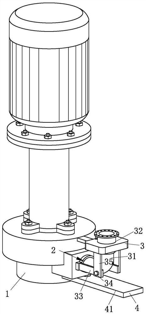
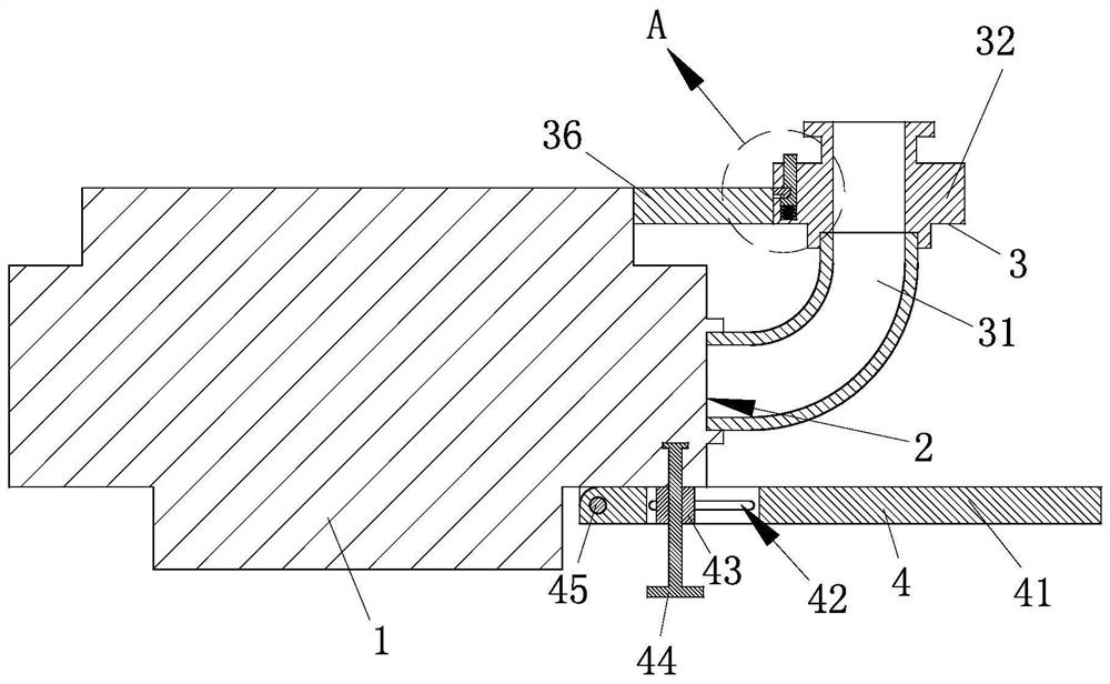
[0017] see Figure 1-3 As shown, a vertical submerged centrifugal pump includes a centrifugal pump body 1, water outlets 2 are provided on both sides of the centrifugal pump body 1, and adjustment structures 3 are respectively provided on both sides of the centrifugal pump body 1, The adjustment structure 3 includes a water-conducting hose 31, a connecting flange 32, a first support rod 33, a first rotating shaft 34 and a second support rod 35, and the side of...


PUM


Abstract

The invention relates to the technical field of centrifugal pumps, in particular to a vertical type submerged centrifugal pump. The vertical type submerged centrifugal pump comprises a centrifugal pump body, a water outlet, an adjusting structure, a water guide hose, a connecting flange, a first supporting rod, a first rotating shaft, a second supporting rod and a supporting structure. The vertical type submerged centrifugal pump has the advantages that the water guide hose is arranged between the connecting flange and the centrifugal pump body, so that the connecting flange used for connecting a drainage pipe can be adjusted at any angle, and when the liquid level of the installation position of the centrifugal pump is low, the angle of the connecting flange can be changed so as to reducethe connecting height of the drainage pipe, and an operator can conveniently install the centrifugal pump; and meanwhile, the first supporting rod and the second supporting rod which are rotationallyconnected are arranged between the connecting flange and the centrifugal pump body, the moving range of the connecting flange can be limited, so that the connecting flange can only rotate on a same plane, the angle of the connecting flange can be conveniently adjusted, and meanwhile, the damage to the water guide hose caused by rotation is reduced, and the water guide hose is prevented from beingbent.

Description

technical field [0001] The invention relates to the technical field of centrifugal pumps, in particular to a vertical submerged centrifugal pump. Background technique [0002] Centrifugal pumps work by rotating the impeller to cause the water to move centrifugally. Before starting the pump, the pump casing and the suction pipe must be filled with water, and then the motor is started to drive the impeller and the water to rotate at a high speed. The water undergoes centrifugal motion and is thrown to the outer edge of the impeller, and flows through the volute pump casing. The pressure water pipeline flowing into the water pump. Centrifugal pumps can be widely used in electric power, metallurgy, coal, building materials and other industries to transport slurry containing solid particles. Such as hydraulic ash removal in thermal power plants, slurry transportation in metallurgical beneficiation plants, coal slurry and heavy medium transportation in coal washing plants, etc. ...

Claims


Application Information

Patent Timeline
Patent Type & Authority Applications(China)
IPC IPC(8): F04D1/00F04D29/42F04D29/62
CPCF04D1/00F04D29/4293F04D29/628
Inventor 梁涛张波王飞
Owner 亚太泵阀有限公司
Why Eureka
Try Eureka