
Multi-link rear suspension, axle assembly and vehicle

A rear suspension, multi-link technology, applied in the direction of suspension, elastic suspension, vehicle parts, etc., can solve the problems of occupying a large chassis space and complex structure, reducing chassis space, reducing structural complexity, reducing The effect of the connection height

Active Publication Date: 2022-01-04
NIO ANHUI HLDG CO LTD
View PDF9 Cites 0 Cited by
  • Summary
  • Abstract
  • Description
  • Claims
  • Application Information

AI Technical Summary

Problems solved by technology

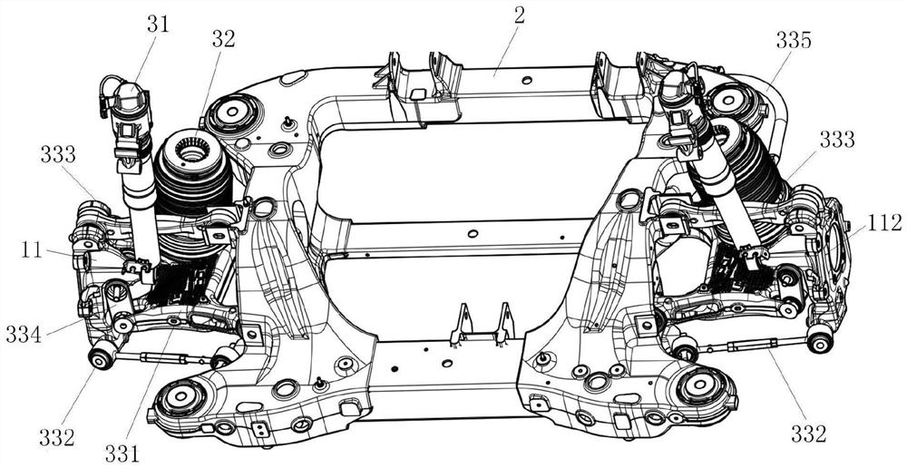
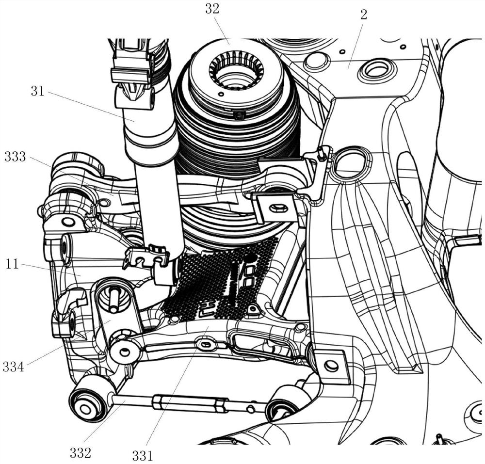
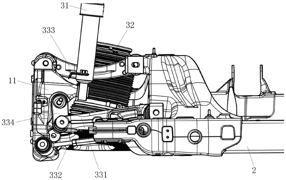
[0005] In order to solve the above-mentioned problems in the prior art, that is, in order to solve the problems of the existing multi-link suspension with complex structure and large chassis space, the present invention provides a multi-link rear suspension. The rod rear suspension includes a shock absorbing mechanism, an elastic mechanism and a connecting rod assembly, the connecting rod assembly includes a first control arm, the two ends of the first control arm are respectively connected with the steering knuckle and the subframe, and the shock absorbing The two ends of the mechanism are respectively connected with the steering knuckle and the vehicle body, the two ends of the elastic mechanism are respectively connected with the first control arm and the vehicle body, and the steering knuckle is provided with a shaft allowing the axle of the wheel to pass through The shock absorbing mechanism is located on one side of the axle hole in the longitudinal direction of the vehicle, and the elastic mechanism is located on the other side of the axle hole in the longitudinal direction

Method used


Image

  • Multi-link rear suspension, axle assembly and vehicle
  • Multi-link rear suspension, axle assembly and vehicle
  • Multi-link rear suspension, axle assembly and vehicle

Examples


Embodiment Construction

[0047] Preferred embodiments of the present invention are described below with reference to the accompanying drawings. Those skilled in the art should understand that these embodiments are only used to explain the technical principles of the present invention, and are not intended to limit the protection scope of the present invention. For example, although the multi-link rear suspension of the present invention is described in conjunction with the rear axle assembly of the vehicle, this application scenario is not static, and those skilled in the art can also apply the present invention to other application scenarios, as long as the The application scene can only install a multi-link rear suspension.

[0048] It should be noted that, in the description of the present invention, the terms "center", "upper", "lower", "left", "right", "vertical", "horizontal", "inner", "outer" etc. The terms of the indicated direction or positional relationship are based on the direction or pos...


PUM


Abstract

The invention relates to the technical field of automobiles, in particular to a multi-link rear suspension, an axle assembly and a vehicle. The invention aims to solve the problems of complex structure and large chassis space occupied by the existing multi-link suspension. For this purpose, the multi-link rear suspension of the present invention, the multi-link rear suspension includes a shock absorbing mechanism, an elastic mechanism and a connecting rod assembly, and the connecting rod assembly includes a first control arm, the two ends of the first control arm are respectively connected to The steering knuckle is connected with the sub-frame, the two ends of the damping mechanism are respectively connected with the steering knuckle and the vehicle body, and the two ends of the elastic mechanism are respectively connected with the first control arm and the vehicle body, and the steering knuckle is provided with a shaft allowing the wheel axle to pass through The shock absorbing mechanism is located on one side of the axle hole in the longitudinal direction of the vehicle, and the elastic mechanism is located on the other side of the axle hole in the longitudinal direction. The invention greatly reduces the structural complexity of the multi-link rear suspension and reduces the occupied space of the multi-link rear suspension.

Description

technical field [0001] The invention relates to the technical field of automobiles, in particular to a multi-link rear suspension, an axle assembly and a vehicle. Background technique [0002] With the rapid development of automobile technology, users have higher and higher requirements for the comfort and handling performance of vehicles. Suspension, as the core component of the automobile chassis, directly determines the handling performance and ride comfort of the vehicle, so the research and development of suspension is very important for major automobile manufacturers. Automobile suspension is divided into independent suspension and non-independent suspension. Multi-link suspension is a kind of independent suspension. Because it has multiple connecting rods and struts, each connecting rod can perform multiple functions on the wheel. Force control, so cars equipped with multi-link suspensions usually have excellent handling performance and ride comfort. [0003] Althou...

Claims


Application Information

Patent Timeline
Patent Type & Authority Patents(China)
IPC IPC(8): B60G21/05B60G7/00B60G21/055B60G15/06B60G15/12
CPCB60G21/05B60G7/00B60G21/055B60G15/067B60G15/12
Inventor 徐哲李徐钢申震戴政马少崇洪宗洲王永泰
Owner NIO ANHUI HLDG CO LTD
Learn More