Supercharge Your Innovation With Domain-Expert AI Agents!

Vaporization system of test box

A test box and box body technology, which is applied in the field of vaporization system, can solve the problems of large space occupation, damage of humidification pipe, low installation efficiency, etc., and achieve the effect of reasonable installation layout, high humidification efficiency and stable steam

Inactive Publication Date: 2021-02-05
CHONGQING ATEC TEST EQUIP
View PDF6 Cites 0 Cited by
  • Summary
  • Abstract
  • Description
  • Claims
  • Application Information

AI Technical Summary

Problems solved by technology

The installation positions of the components of the discrete humidification system are installed in different positions of the equipment according to the structure of the equipment. The connecting pipelines of the humidification boiler, water supply system, filtration system, overflow water system, drainage system, pure water tank, etc. are messy and complicated. Low installation efficiency and lack of aesthetics of industrial equipment
Although the integrated humidification system integrates all the accessories related to the humidification system into a relatively concentrated structural frame, due to the inherent factors such as the humidification boiler and the water storage tank, the integrated humidification system has a large size and takes up a lot of space. As a result, it is not conducive to the matching installation with the test box
Both of the above two humidification systems use the method that the electric heating tube directly contacts the water to raise the temperature of the water and let it reach a state of vaporization and boiling, thereby producing water vapor, but this method is prone to quality problems due to the humidification tube itself ( The surface heat load is too high) or the user's water supply problem (high water hardness) and other factors lead to damage to the humidification pipe or leakage, which causes the environmental test chamber to fail to operate normally

Method used


Image

  • Vaporization system of test box
  • Vaporization system of test box
  • Vaporization system of test box

Examples


Embodiment Construction

[0017] The present invention will be described in further detail below in conjunction with specific embodiments and accompanying drawings.

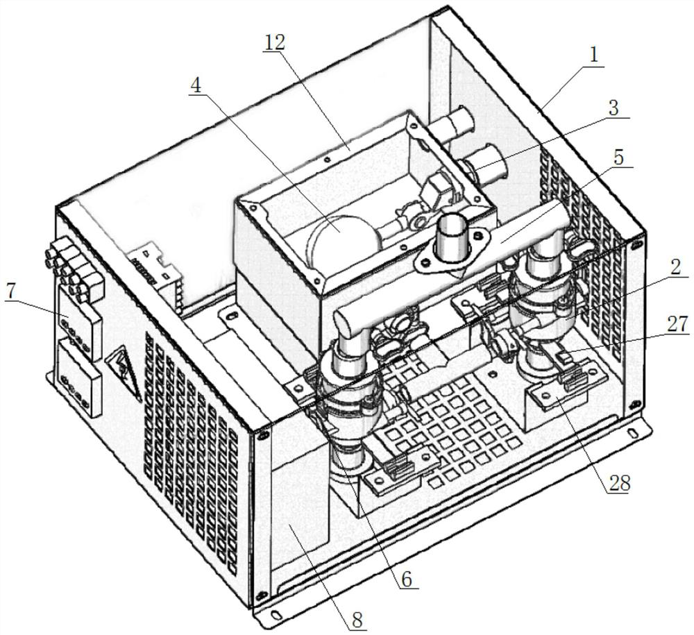
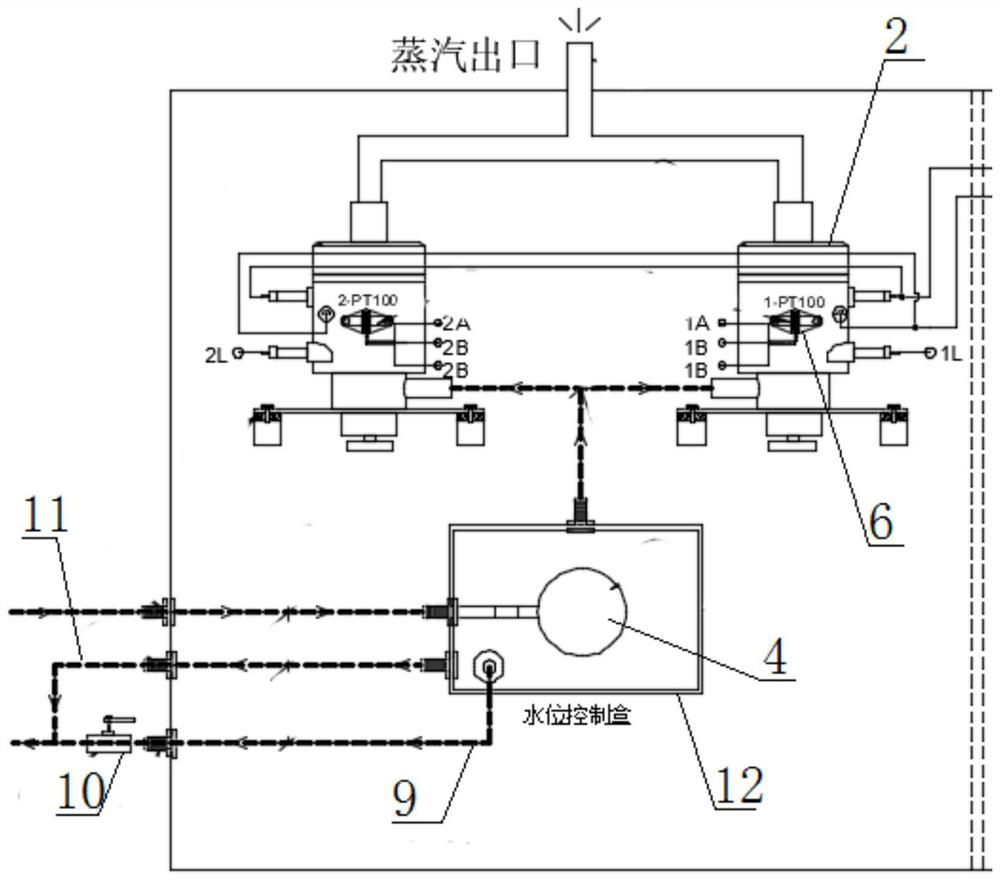
[0018] a kind of like Figure 1-4 The vaporization system of the test box shown includes a water storage box 12 arranged in the box body 1, and two heating devices 2 arranged in parallel, and the water storage box 12 and the heating device 2 are both arranged in the box body through a bracket. 1, the water storage box 12 is located on one side of the heating device 2, and the lower part of the water storage box 12 is provided with water inlet pipes respectively connected to the lower water inlets of the two heating devices 2, that is, the storage The water in the water box 12 can directly enter the heating device 2 . The upper part of the water storage box 12 has a water filling port 3, and a ball float valve 4 for controlling the opening and closing of the water filling port 3 is also arranged in the water storage box 12, by which the w...


PUM


Abstract

The invention discloses a vaporization system of a test box. The system is characterized by comprising a water storage box arranged in a box body and two heating devices arranged in parallel, the lower part of the water storage box is provided with a water inlet pipeline which is respectively communicated with lower water inlets of the two heating devices, and the upper part of the water storage box is provided with a water adding port; and a floating ball valve for controlling the water adding port to be opened and closed is further arranged in the water storage box, the water level in the water storage box is consistent with the water level in heating cavities of the heating devices, and steam outlets at the upper portions of the two heating devices are connected through a steam converging pipe and converged into one path to extend out of the box body. Each heating device is provided with a temperature sensor, and the temperature sensors are electrically connected to an intelligent temperature controller arranged on the box body. The invention has the beneficial effects that the whole vaporization system is reasonable in installation and layout among components, compact in spaceamong the components, high in humidification efficiency, high in speed and stable in steam production, and has independent and complete product attributes.

Description

technical field [0001] The invention relates to the field of environmental test chambers, in particular to a vaporization system of a test chamber. Background technique [0002] When the conventional environmental test chamber simulates a humid environment, a humidifier is usually used. The conventional humidification method uses an electric heating tube to directly contact the water. After the water is heated to boiling (the latent heat vaporization phenomenon occurs in the water), the water vapor generated by the vaporization is introduced into the In the environment box, so as to achieve the purpose of creating a humid environment. Conventional humidifiers in environmental test chambers are usually divided into two types: discrete (humidification boiler is separated from water supply, filtration system, etc.) and integrated. The installation positions of the components of the discrete humidification system are installed in different positions of the equipment according t...

Claims


Application Information

Patent Timeline
Patent Type & Authority Applications(China)
IPC IPC(8): F22B1/28F22B33/18
CPCF22B1/28F22B33/18
Inventor 汪洋谢绍军彭祥友
Owner CHONGQING ATEC TEST EQUIP
Features
  • R&D
  • Intellectual Property
  • Life Sciences
  • Materials
  • Tech Scout
  • Unparalleled Data Quality
  • Higher Quality Content
  • 60% Fewer Hallucinations
Learn More