Supercharge Your Innovation With Domain-Expert AI Agents!

Flue structure and installation method of new economizer

An economizer and flue technology, which is applied to combustion methods, exhaust gas devices, feed water heaters, etc., can solve the problems of cumbersome flue maintenance, inability to meet new structural design requirements, and inability to implement inclined flue suspension.

Active Publication Date: 2021-08-20
HARBIN BOILER CO LTD
View PDF6 Cites 0 Cited by
  • Summary
  • Abstract
  • Description
  • Claims
  • Application Information

AI Technical Summary

Problems solved by technology

[0002] With the increasingly fierce market competition, new products emerge one after another, and the layout of the boiler tail flue is also different. The traditional economizer flue guard is hung vertically on the tail wall header. There is no truss inside the flue, and all flue gas Duct load needs to be transferred to the header by the guard plate, the inspection and maintenance of the flue is cumbersome, the arrangement of the flue is messy, and the structure is complex
[0003] At the same time, as an integral part of the tail flue, the temperature-adjusting baffle is welded together with the flue, but this structure relying on vertical hanging cannot meet the design requirements of the new structure. The economizer needs to be hung under the wall-clad header, and the flue The flue must be hung on the tail wall header at a certain angle, and the traditional economizer flue structure cannot realize the suspension of the inclined flue

Method used


Image

  • Flue structure and installation method of new economizer
  • Flue structure and installation method of new economizer
  • Flue structure and installation method of new economizer

Examples


Embodiment 1

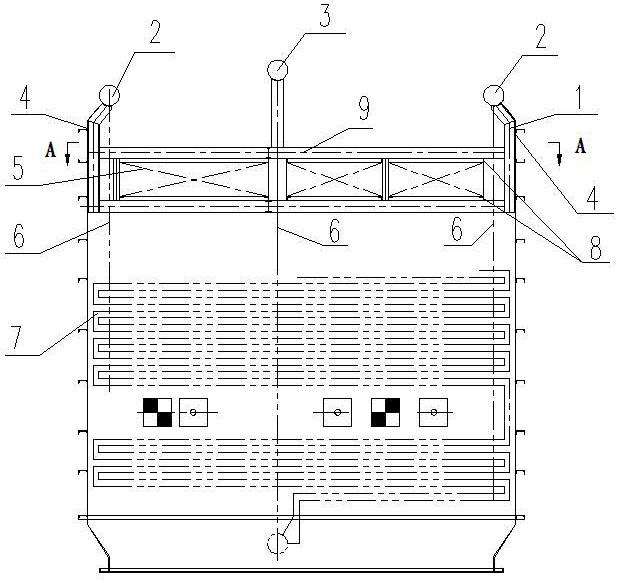
[0025] A new economizer flue structure, its composition includes: flue structure, the flue structure includes truss A1, truss B9, guard plate 4, angle steel slideway 8, the truss A and the wall header 2 Fix by welding and design the inclination angle a, the angle a is 0~45°, the side of the truss A is equipped with guard plates, the truss A and the truss B form an integral frame structure in the flue , the position of the baffle plate 5 of the truss A is provided with an angle steel that runs through the width direction of the flue, and the angle steel is welded on the inner side of the truss A and the guard plate as the support frame of the baffle plate, so The above-mentioned baffle is placed on the angle steel of the truss A, and the above-mentioned angle steel is the angle steel slideway when the boiler shutdown maintenance needs to draw out the baffle.

Embodiment 2

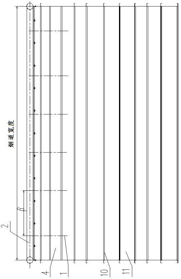
[0027] According to the new economizer flue structure described in Embodiment 1, the middle part of the truss A is equipped with a partition wall header 3, the number of the truss A is one group and the distance between them is β, and the distance β is 2m-3m.

Embodiment 3

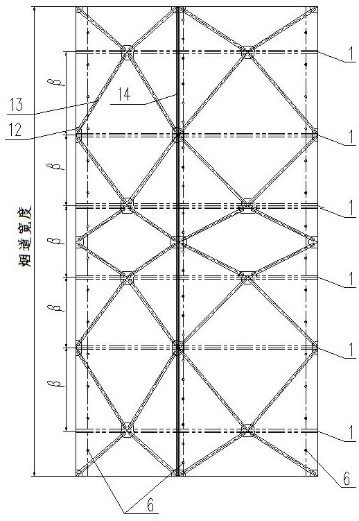
[0029] According to the novel economizer flue structure described in Example 2, the guard plate includes a set of section steel 10, steel plates 11 are welded between the section steel, the truss B includes I-beam 14, and the The I-beams are respectively connected to the steel pipes 13 through the connecting plates 12, the trusses A are respectively connected to the steel pipes through the connecting plates, and the steel pipes are arranged in a herringbone shape.


PUM


Abstract

A novel economizer flue structure and installation and arrangement method. The traditional economizer flue guard plate is hung vertically on the tail wall header. There is no truss inside the flue duct, and all flue loads must be transmitted to the header by the guard plate. The composition of the present invention includes: flue structure, the flue structure includes truss A (1), truss B (9), guard plate (4), angle steel slideway (8), truss A and wall header (2) are welded Fix and design the inclination angle a, the angle a is 0~45°, the guard plate is installed on the side of truss A, truss A and truss B form an integral frame structure in the flue, and the baffle plate (5) of truss A is set up and down through the smoke The angle steel in the width direction of the track, the angle steel is welded on the inner side of the truss A and the guard plate as the supporting frame of the baffle, and the baffle is placed on the angle steel of the truss A. When the boiler shuts down and needs to be pulled out for maintenance, the angle steel is an angle steel slideway. The invention is used for the flue structure of a novel coal economizer.

Description

Technical field: [0001] The invention relates to a novel economizer flue structure and an installation and arrangement method. Background technique: [0002] With the increasingly fierce market competition, new products emerge one after another, and the layout of the boiler tail flue is also different. The traditional economizer flue guard is hung vertically on the tail wall header. There is no truss inside the flue, and all flue gas The load of the duct needs to be transmitted to the header by the guard plate, the inspection and maintenance of the flue is cumbersome, the arrangement of the flue is messy, and the structure is complex. [0003] At the same time, as an integral part of the tail flue, the temperature-adjusting baffle is welded together with the flue, but this structure relying on vertical hanging cannot meet the design requirements of the new structure. The economizer needs to be hung under the wall-clad header, and the flue The flue must be suspended at a cer...

Claims


Application Information

Patent Timeline
Patent Type & Authority Patents(China)
IPC IPC(8): F22D1/06F23J11/00
CPCF22D1/06F23J11/00
Inventor 于凯王丽新吕健
Owner HARBIN BOILER CO LTD
Features
  • R&D
  • Intellectual Property
  • Life Sciences
  • Materials
  • Tech Scout
  • Unparalleled Data Quality
  • Higher Quality Content
  • 60% Fewer Hallucinations
Learn More