Freezing dryer applied to laboratory
A technology for freeze dryers and laboratories, applied in dryers, drying solid materials, drying chambers/containers, etc., can solve the problem of unstable connection between the connecting pipe and the body, failure to meet freeze-drying requirements, and decline in freeze-drying effects, etc. problem, to achieve the effect of improving the carrying efficiency, improving the aesthetics and improving the stability
- Summary
- Abstract
- Description
- Claims
- Application Information
AI Technical Summary
Problems solved by technology
Method used
Image
Examples
Embodiment 1
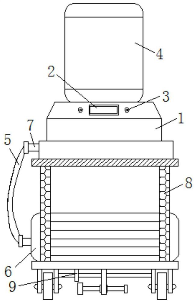
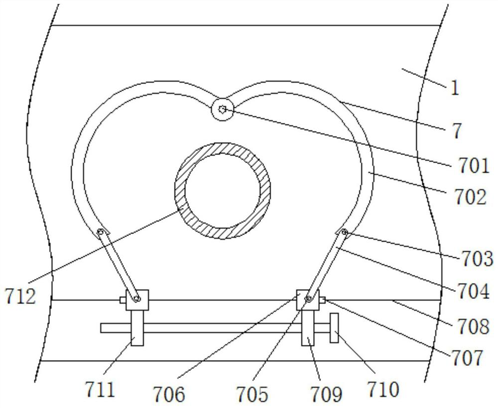
[0028] Such as figure 1 and 5 As shown, the present invention provides a freeze dryer applied in a laboratory, comprising: a body 1, a display screen 2, buttons 3, a drying chamber 4, a connecting pipe 5, a vacuum pump 6, a reinforcement mechanism 7, a first rotating shaft 701, a clamp Ring 702, first movable shaft 703, connecting plate 704, second movable shaft 705, connecting block 706, first sliding block 707, first chute 708, first threaded block 709, threaded rod 710, second threaded block 711 , connecting port 712, carrying mechanism 8, top plate 801, second chute 802, second slider 803, splint 804, pole 805, bottom plate 806, movable wheel 807, second rotating shaft 808, reel 809, spring 810 , lifting positioning mechanism 9, fixed screw block 901, rotating rod 902, first bevel gear 903, second bevel gear 904, cross bar 905, vertical plate 906, first gear plate 907, second gear plate 908, bearing 909 and Hand-tightening screw 910; a display screen 2 is installed on th...
Embodiment 2
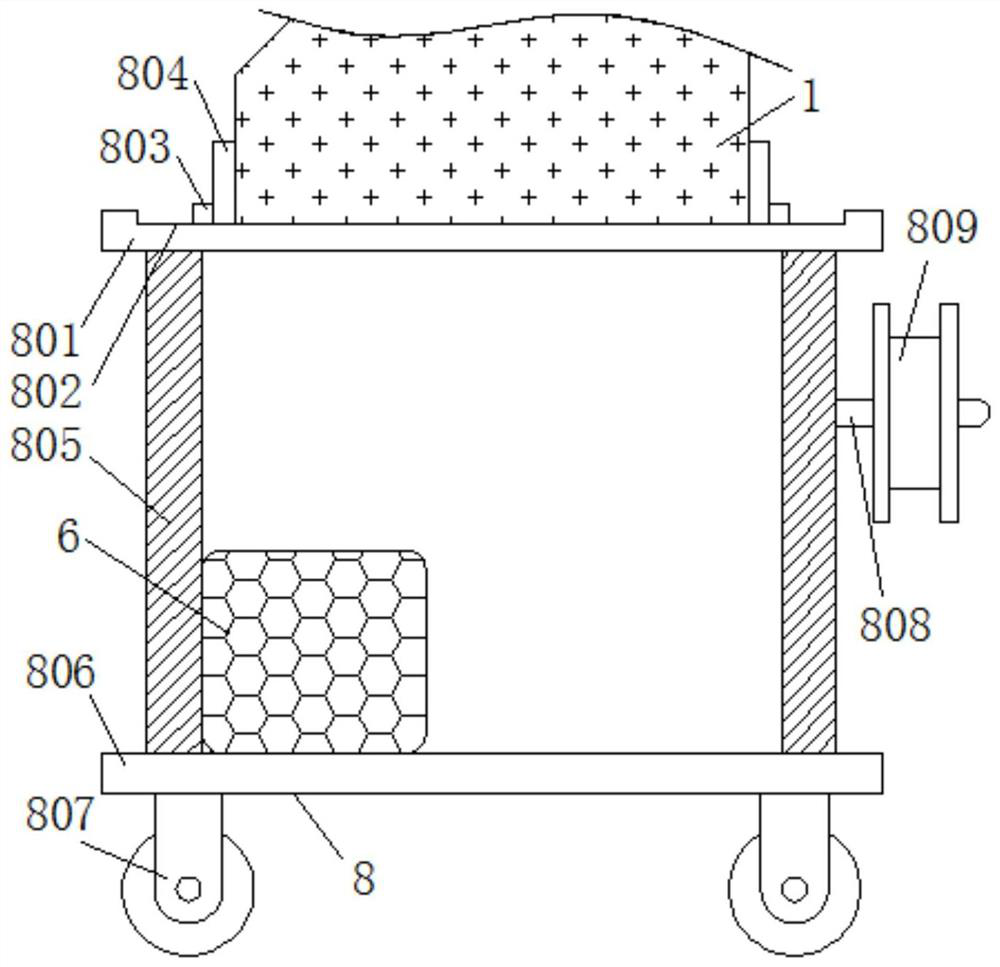
[0035] Such as Figure 3-Figure 4 As shown, this embodiment provides a freeze dryer applied in a laboratory. The difference from Embodiment 1 is that the interior of the carrying mechanism 8 includes a top plate 801; the top of the top plate 801 is provided with a second slide Slot 802; the top of the second chute 802 is slidably installed with a second slider 803; one side of the second slider 803 is fixedly connected with a splint 804; the bottom end of the top plate 801 is fixedly installed with a vertical rod 805 The bottom end of the vertical rod 805 is connected with a base plate 806; the bottom of the base plate 806 is equipped with a movable wheel 807; the top outside of the vertical rod 805 is equipped with a second rotating shaft 808; the outer wall of the second rotating shaft 808 rotates A winding drum 809 is connected, and a spring 810 is installed on the outside of the splint 804 .
[0036] Preferably, in one of the preferred technical solutions of this embodime...
Embodiment 3
[0041] Such as Figure 5 As shown, this embodiment provides a freeze-drying machine applied in a laboratory. The difference from Embodiment 2 is that the inside of the lifting positioning mechanism 9 includes a fixing screw 901; the inner wall of the fixing screw 901 A rotating rod 902 is threadedly connected, and the bottom of the rotating rod 902 is equipped with a first bevel gear 903; The side is fixedly equipped with a cross bar 905; the outer wall of the cross bar 905 is rotatably connected with a vertical plate 906, and one side of the vertical plate 906 is equipped with a first gear plate 907; the first gear plate 907 and the cross bar 905 The outer wall is fixedly connected, and the bottom end of the first gear plate 907 is engaged with a second gear plate 908; one side of the second gear plate 908 is fixedly connected with a thumb screw 910; A bearing 909 is installed in rotation on the outer wall; the bearing 909 is installed at the bottom of the vertical plate 906...
PUM
 Abstract
Description
Claims
Application Information
 - R&D
- Intellectual Property
- Life Sciences
- Materials
- Tech Scout
- Unparalleled Data Quality
- Higher Quality Content
- 60% Fewer Hallucinations
Browse by: Latest US Patents, China's latest patents, Technical Efficacy Thesaurus, Application Domain, Technology Topic, Popular Technical Reports.
© 2025 PatSnap. All rights reserved.Legal|Privacy policy|Modern Slavery Act Transparency Statement|Sitemap|About US| Contact US: help@patsnap.com


