Superconducting cable fault detection method and system

A superconducting cable, fault detection technology, applied in the direction of detecting faults by conductor type, fault location, measuring electricity, etc.

Pending Publication Date: 2021-02-05
SHANGHAI MUNICIPAL ELECTRIC POWER CO +2
View PDF0 Cites 0 Cited by
  • Summary
  • Abstract
  • Description
  • Claims
  • Application Information

AI Technical Summary

Problems solved by technology

[0004] The present invention proposes a fault detection method and system for superconducting cables to

Method used


Image

  • Superconducting cable fault detection method and system
  • Superconducting cable fault detection method and system
  • Superconducting cable fault detection method and system

Examples


Embodiment approach

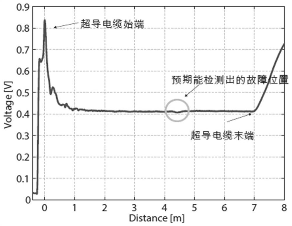
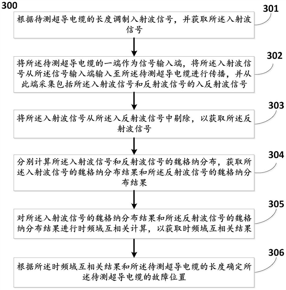
[0127] In the embodiment of the present invention, taking a detection of a 10m-long superconducting cable as an example, the fault point is set at a position of 4.7m. Specifically, the steps for determining the fault location include:

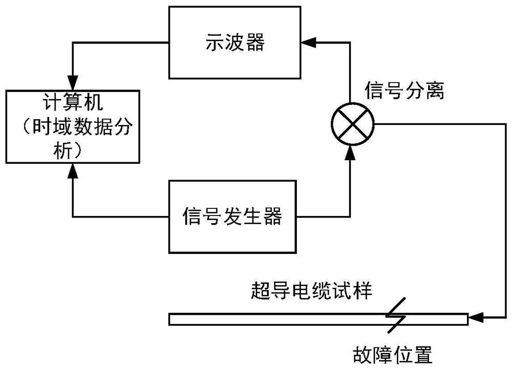
[0128] (1) Generation and injection of incident waveforms

[0129] Among them, the signal generator is used to output the coded pulse chirp wave, and the parameters are respectively w 0 =2π*10 8 , β=2*10 16 , α=2*10 16 , the output waveform is as Figure 6 shown.

[0130] (2) Extraction of reflected waveform

[0131] After the incident waveform is injected into the superconducting cable, the incident reflected wave is obtained. To extract the reflected waveform, first remove the incident wave and the DC component in the reflected signal, and shift the incident signal so that the first peaks of the two waveforms are aligned, and the waveform is obtained as Figure 8 As shown, the larger amplitude is the incident wave, and the smaller amp...


PUM


Abstract

The invention discloses a superconducting cable fault detection method and system; the method comprises the steps: modulating an incident wave signal according to the length of a to-be-detected superconducting cable, and obtaining the incident wave signal; inputting the incident wave signal from the signal input end to the superconducting cable to be tested for propagation, and collecting a reflected wave signal from the signal input end; removing the incident wave signal from the incident and reflected wave signal to obtain a reflected wave signal; respectively calculating Wigner distributionof the incident wave signal and the reflected wave signal, and obtaining a Wigner distribution result of the incident wave signal and a Wigner distribution result of the reflected wave signal; performing time-frequency domain cross-correlation calculation on the Wigner distribution result of the incident wave signal and the Wigner distribution result of the reflected wave signal to obtain a time-frequency domain cross-correlation result; and determining the fault position of the superconducting cable to be measured according to the time-frequency domain cross-correlation result and the lengthof the superconducting cable to be measured.

Description

technical field [0001] The invention relates to the technical field of high-temperature superconducting cable fault diagnosis, and more specifically, to a superconducting cable fault detection method and system. Background technique [0002] With the development of high-temperature superconducting technology, the application of high-temperature superconducting cables in urban power grids has gradually become possible. Due to the structural differences between HTS cables and traditional XLPE cables, it is difficult to directly apply the fault detection and diagnosis technology for traditional cables to superconducting cables. The composition of the insulating medium is different, resulting in different attenuation laws of the propagation speed of the incident signal in the medium, which makes it difficult for the traditional time-domain step waveform method for fault detection to produce reflections of obvious fault points. The detection principle and results of the tradition...

Claims


Application Information

Patent Timeline
IPC IPC(8): G01R31/08
CPCG01R31/083G01R31/088
Inventor 姚周飞杜习周王伟张勇王瑶瑶吴建东谢伟郑健
Owner SHANGHAI MUNICIPAL ELECTRIC POWER CO
Why Eureka
Try Eureka