

Optical cable fiber core network monitoring system
A network monitoring and optical cable technology, applied in transmission systems, electromagnetic wave transmission systems, electrical components, etc., can solve the problems of slow optical cable fault detection response, inaccurate fault detection points, unfavorable applications, etc., to accurately determine the optical cable fault location, The effect of eliminating safety hazards and reducing workload
- Summary
- Abstract
- Description
- Claims
- Application Information
AI Technical Summary
Problems solved by technology
Method used
Image

Examples
Embodiment 1
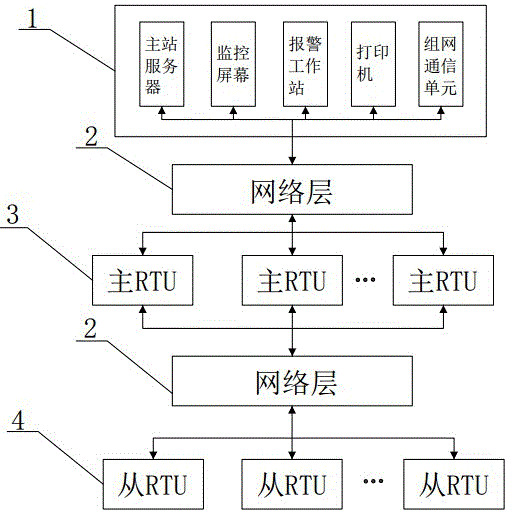
[0034] The network structure of the present invention such as figure 1 As shown, it includes application layer 1, network layer 2 and terminal layer, wherein the terminal layer includes master RTU3 and slave RTU4. The network layer 2 forms a communication network through optical modems and optical fibers, and is set between the application layer 1 and the master RTU3, and between the master RTU3 layer and the slave RTU4, and is used for data communication between different network layers.
[0035] Application layer 1 includes the MTC master station located in the monitoring center of the power company. The MTC master station includes the master server, monitoring screen, alarm workstation, printer and networking communication unit, the master server, monitoring screen, alarm workstation, printer and group The network communication unit performs data communication with the network layer 2 through the industrial Ethernet communication port. The master station server includes a ...
Embodiment 2
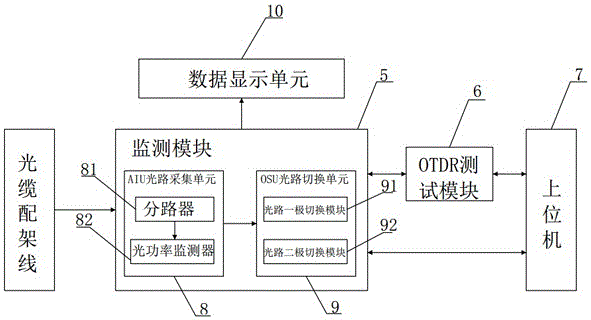
[0042] Such as image 3 As shown, the difference between this embodiment and Embodiment 1 is that the remote optical fiber monitoring device further includes a data display unit 10 . The signal input end of the data display unit 10 is electrically connected to the output end of the monitoring module 5, and the data display unit 10 can display the operating status information of the optical fiber core of the optical cable collected by the monitoring module 5 on the spot, so that maintenance personnel can intuitively observe the state of the optical fiber. run information.
Embodiment 3
[0044] Such as Figure 4 As shown, the difference between this embodiment and Embodiment 2 is that the remote optical fiber monitoring device also includes an alarm unit 11, and the alarm unit 11 adopts a rotary sound and light alarm. In case of abnormality, the rotary sound and light alarm will send out sound and light alarm to warn the workers.
PUM
 Abstract
Description
Claims
Application Information