Thermal-solid-electromagnetic three-field coupling calculation method of reflector antenna

A calculation method and reflector technology, applied in design optimization/simulation, special data processing applications, etc., can solve problems such as limited use, complex operating environment of reflector antennas, and unsuitable for engineering design and development stages, and achieve operability. strong effect

Active Publication Date: 2021-02-05
NO 54 INST OF CHINA ELECTRONICS SCI & TECH GRP
View PDF11 Cites 0 Cited by
  • Summary
  • Abstract
  • Description
  • Claims
  • Application Information

AI Technical Summary

Problems solved by technology

This method is only some preliminary performance estimation. For large-scale and high-precision reflector antennas, this method will cause very large errors in calculation results and cannot truly reflect the three-field coupling problem. It has the following defects:
For reflector antennas with different calibers, different types, different geographical locations, and different materials that appear in the project, there is a lack of reference values
[0007] (2) The numerical simulation analysis of the temperature field given in the existing literature is too cumbersome, especially in order to reduce the amount of calculation, the model has been simplified a lot, and for the conduction, radiation and convection in the thermal analysis process, do A lot of assumptions are made, which reduces the credibility of the calculation results
[0008] (3) Some literatures mention the use of temperature sensors to measure the antenna temperature, but this method is not operable in the design demonstration stage
[0009] (4) The prior art does not provide a three-field coupling analysis method
Due to the many uncertainties in the modeling process and the influence of environmental factors, the error of the calculation results will increase.
[0013] (3) The method of determining the temperature field through measured data is not suitable for the design and development stage of the project
The structure composition and operating environment of the reflector antenna are complex, which limits the use of existing software processes
[0017] (3) The application background of the above methods and the reflector antenna belong to different fields, and the methods and processes cannot meet the performance analysis of the reflector antenna

Method used


Image

  • Thermal-solid-electromagnetic three-field coupling calculation method of reflector antenna
  • Thermal-solid-electromagnetic three-field coupling calculation method of reflector antenna
  • Thermal-solid-electromagnetic three-field coupling calculation method of reflector antenna

Examples


Embodiment Construction

[0076] The present invention will be further described below in conjunction with the accompanying drawings and specific embodiments.

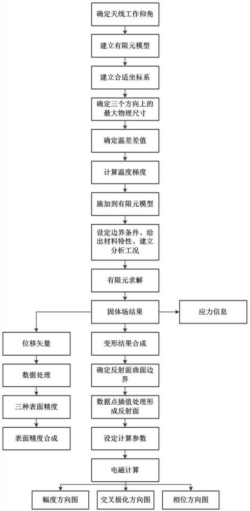
[0077] In this embodiment, the circular symmetric reflector antenna and the offset dual reflector antenna are taken as examples, and the overall process is as follows figure 1 shown, including the following steps:

[0078] (1) Determine the working elevation angle of the reflector antenna.

[0079] The working elevation angle of the antenna in the embodiment is 5°-90°.

[0080] (2) Establish the antenna finite element model in FEA software.

[0081] FEA software can be used such as: Ansys, Patran, HyperMesh, etc.

[0082] (3) The finite element model in step (2) establishes a suitable coordinate system OXYZ.

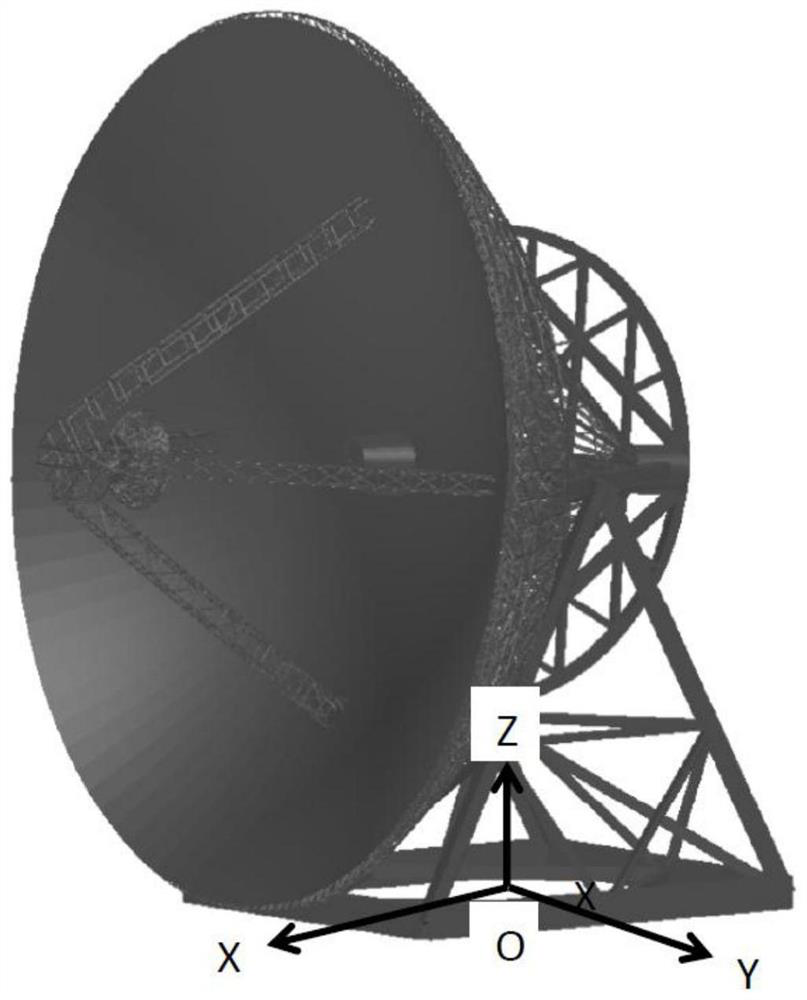
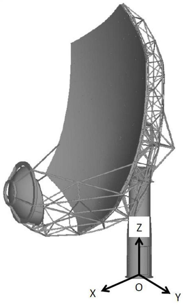
[0083] figure 2 It is a schematic diagram of the coordinate system of the circular symmetric reflector antenna in the embodiment; image 3 is a schematic diagram of the coordinate system of the offset reflector antenna in the embod...


PUM


Abstract

The invention discloses a thermal-solid-electromagnetic three-field coupling calculation method of a reflector antenna, relates to the technical field of reflector antenna analysis, and aims to provide a calculation method with high precision, simplicity and strong practicability. The calculation method mainly comprises the following steps: establishing an antenna finite element model, calculatingtemperature gradient distribution in different directions, obtaining a solid field result, and analyzing and synthesizing surface precision; and performing processing and electromagnetic analysis onthe reflecting surface and the feed source deformation data, so that coupling of the reflecting surface antenna from a thermal field to a solid field and an electromagnetic field is realized. Comparedwith the prior art, the method has the characteristics of high precision, short period and simplicity and convenience in data processing, and is particularly suitable for design, index budget and check of various reflector antennas.

Description

technical field [0001] The present invention relates to the technical field of reflector antenna analysis, in particular to a thermoset electromagnetic three-field coupling calculation method for reflector antennas, which can be used for thermal fields or temperature fields, solid fields and electromagnetic fields of single reflector antennas or double reflector antennas The coupling calculation is especially suitable for the index budget and performance analysis of the reflector antenna. Background technique [0002] Reflector antennas are widely used in the fields of communication, measurement and control, and radio astronomy because of their strong directivity. For reflector antennas, especially reflector antennas that work in high frequency bands, in the process of design and demonstration, it is necessary to accurately estimate its various technical indicators. Among them, the most critical is the influence of temperature on the surface accuracy of the antenna and its c...

Claims


Application Information

Patent Timeline
Patent Type & Authority Applications(China)
IPC IPC(8): G06F30/23
CPCG06F30/23
Inventor 刘国玺伍洋杜彪刘胜文郑元鹏陈隆
Owner NO 54 INST OF CHINA ELECTRONICS SCI & TECH GRP
Why Eureka
Try Eureka