Motor stator and motor

A technology of motor stator and stator iron core, which is applied in the direction of electrical components, electromechanical devices, electric components, etc., can solve the problems of complicated manufacturing process, complicated arrangement, and inconsistent twisting direction or twisted slot spacing of welding ends.

Inactive Publication Date: 2021-02-05
TIANJIN SANTROLL ELECTRIC AUTOMOBILE TECH CO LTD
View PDF0 Cites 2 Cited by
  • Summary
  • Abstract
  • Description
  • Claims
  • Application Information

AI Technical Summary

Problems solved by technology

[0002] The stator winding includes a plurality of hairpin conductors, which are arranged in a certain way. Various types of conductors include U-shaped conductors and S-shaped conductors, which penetrate into the slots of the stator core to form the three-phase motor required. Windings, there are many types of hairpin conductors used in the prior art, and the arrangement method is complicated, and a large number of bus bars and bus bars are needed to connect the branches and neutral points of each phase winding;
[0003] More than 90% of the stator windings in the prior art have the number of slots per pole and phase greater than or equal to 2, but if the phases of the stator winding are connected in series, there will be twisting directions or twisting of the welding ends located in the same layer of slots Inconsistent groove spacing, complicated manufacturing process, difficult forming, high production cost and low processing efficiency

Method used


Image

  • Motor stator and motor
  • Motor stator and motor
  • Motor stator and motor

Examples


Embodiment Construction

[0043] The present invention will be further described in detail below in conjunction with the accompanying drawings and embodiments. It should be understood that the specific embodiments described here are only used to explain the present invention, but not to limit the present invention. In addition, it should be noted that, for the convenience of description, only some structures related to the present invention are shown in the drawings but not all structures.

[0044] It should be noted that the terms "first" and "second" in the specification, claims and drawings of the present invention are used to distinguish different objects, rather than to limit a specific order. The following embodiments of the present invention may be implemented independently, or may be implemented in combination with each other, which is not specifically limited in the embodiments of the present invention.

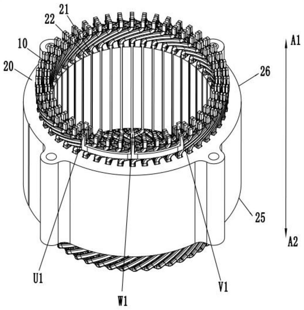
[0045] The invention provides a motor stator. figure 1The extension direction of A1A2 i...


PUM


Abstract

The invention provides a motor stator and a motor, wherein the motor stator comprises a stator winding which comprises a plurality of phase windings installed on a stator core, and enables each grooveto be divided into M layers through the number of grooves accommodated in the radial direction of the stator core; the transformer is characterized in that each phase winding comprises a first conductor group, a plurality of second conductor groups, a plurality of third conductor groups and a fourth conductor group which are connected in series. According to the technical scheme of the motor stator in the embodiment of the invention, a bus bar connected in series among all phases of windings in related technologies is canceled, and the first conductor group, the second conductor group, the third conductor group and the fourth conductor group of each phase of winding can be directly connected, so that each phase of winding and a neutral point can be arranged in any slot and any layer of the winding; complexity of a manufacturing process is reduced, production cost is reduced, material cost is reduced, and machining efficiency is improved.

Description

technical field [0001] The invention relates to the field of motors, in particular to a motor stator and a motor. Background technique [0002] The stator winding includes a plurality of hairpin conductors, which are arranged in a certain way. Various types of conductors include U-shaped conductors and S-shaped conductors, which penetrate into the slots of the stator core to form the three-phase motor required. Windings, there are many types of hairpin conductors used in the prior art, and the arrangement method is complicated, and a large number of bus bars and bus bars are needed to connect the branches and neutral points of each phase winding; [0003] More than 90% of the stator windings in the prior art have the number of slots per pole and phase greater than or equal to 2, but if the phases of the stator winding are connected in series, there will be twisting directions or twisting of the welding ends located in the same layer of slots The groove spacing is inconsiste...

Claims


Application Information

Patent Timeline
IPC IPC(8): H02K1/16H02K3/04H02K3/28H02K3/12H02K3/50
CPCH02K1/165H02K3/04H02K3/12H02K3/28H02K3/50H02K2213/03
Inventor 杨伟达
Owner TIANJIN SANTROLL ELECTRIC AUTOMOBILE TECH CO LTD
Why Eureka
Try Eureka