Driving circuit for plant illumination

A driving circuit, plant lighting technology, applied in the direction of electrical components, etc., can solve the problems of unable to work normally, unable to obtain accurate LED current, etc., to achieve the effect of being beneficial to photosynthesis and reducing the difficulty of design

Pending Publication Date: 2021-02-05
4D BIOS INC
View PDF0 Cites 1 Cited by
  • Summary
  • Abstract
  • Description
  • Claims
  • Application Information

AI Technical Summary

Problems solved by technology

In order to solve the technical problem that the existing driving scheme cannot work normally in high-frequency chopping occasions, or cannot obtain high-precision LED current, the present invention proposes a driving circuit for plant lighting. The specific steps of the present invention are as follows The technical solution is realized

Method used


Image

  • Driving circuit for plant illumination
  • Driving circuit for plant illumination
  • Driving circuit for plant illumination

Examples


Embodiment 2

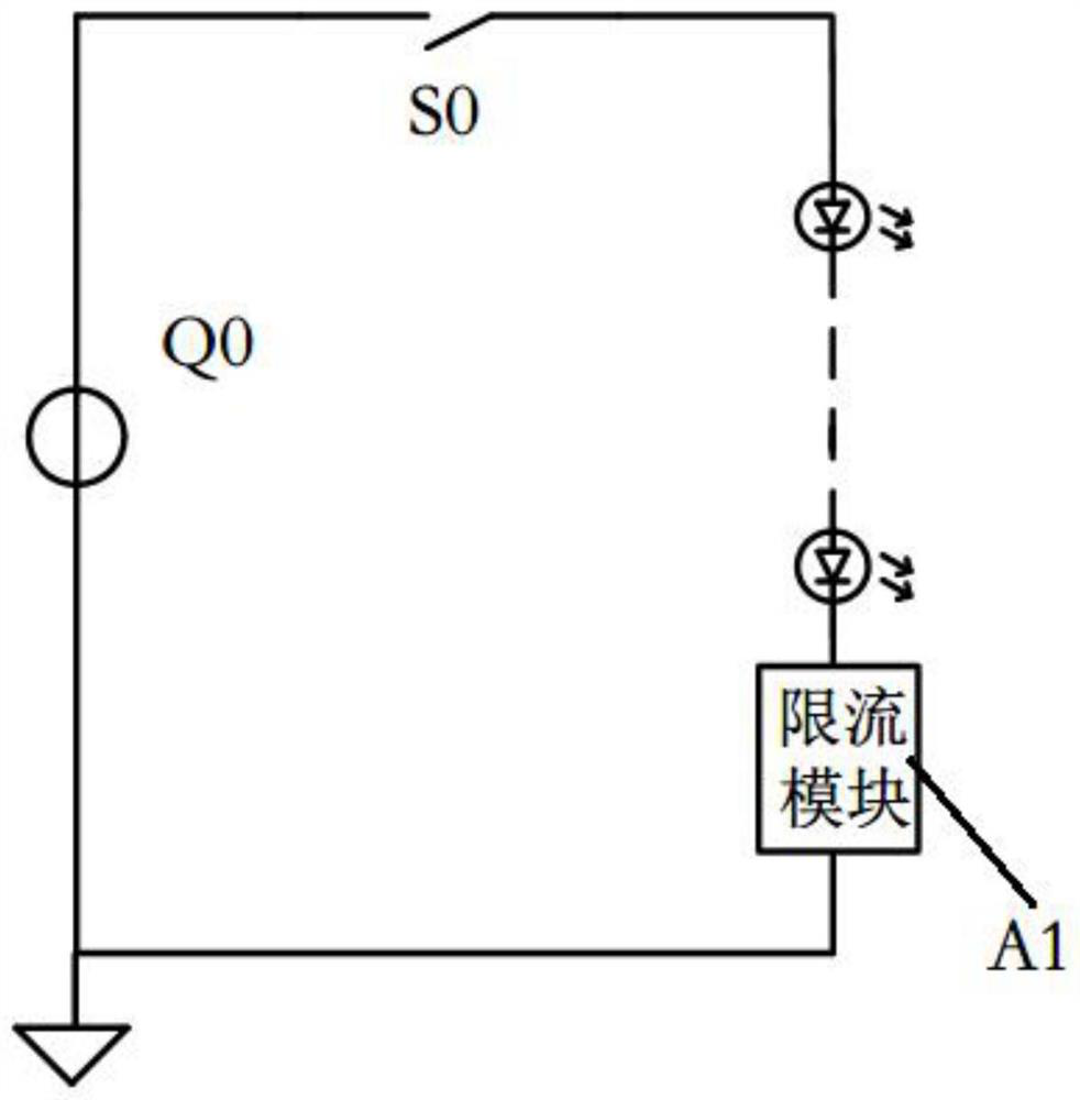
[0057] In Embodiment 2, the drive circuit for plant lighting may include multiple adjustable circuits, and the multiple adjustable circuits are used to connect multiple groups of loads in one-to-one correspondence. Such as Figure 8 As shown, n adjustable circuits are used to connect n groups of loads one by one. When there are n LED lamp loads, each LED lamp load corresponds to a chopper switch and an adjustable voltage source. Multiple LED loads share A constant voltage source Qs. In the multi-output drive circuit, the voltage of each LED lamp is allowed to be different. Through the voltage adjustment at both ends of the adjustable voltage source in each branch, the voltage difference of the LED lamp of this road is made up, so that the voltage of each LED lamp can be adjusted. The sum of the voltage source and the LED lamp voltage is equal to the parameter voltage of the constant voltage source. Each group of LED loads may include multiple LED lamps connected in series. ...


PUM


Abstract

In order to solve the technical problem that an existing driving scheme cannot work normally in a high-frequency chopping occasion or cannot obtain high-precision LED current, the invention provides adriving circuit for plant illumination. The driving circuit comprises a constant voltage source and an adjustable circuit, and the first end of the constant voltage source is used for being connectedwith the first end of a load. The adjustable circuit comprises: an adjustable voltage source, wherein the first end of the adjustable voltage source is connected with the second end of the constant voltage source; a chopper switch, wherein the first end of the chopper switch is connected with the second end of the adjustable voltage source, and the second end of the chopper switch is used for being connected with the second end of the load; and a control circuit, wherein the first end of the control circuit is used for being connected with the first end of the load, the second end of the control circuit is connected with the third end of the chopper switch, the third end of the control circuit is connected with the third end of the adjustable voltage source, and the control circuit is used for controlling the chopper switch and controlling the voltage of the adjustable voltage source according to a load current signal in order to match the sum of the voltage of the adjustable voltagesource and the voltage of the constant voltage source with a target voltage.

Description

technical field [0001] The invention relates to the field of circuit electronics, in particular to a driving circuit for plant lighting. Background technique [0002] In the field of plant lighting, often used such as figure 1 The drive circuit shown is used to power LED lamps for plant lighting. The switch S0 acts as a chopping switch, so that the DC received by the LED lamp is a high-frequency chopping DC, and the current waveform is as follows: figure 2 shown. For better photosynthesis of plants, or more efficient use of lighting power, the frequency f of the chopping switch S0 is usually above MHz. [0003] exist figure 1 In the drive circuit, the constant voltage source Q0 of the previous stage outputs a direct current with a constant voltage amplitude, and in order to stabilize the brightness of the LED lamp, it is necessary to connect the current limiting module A1 in series in the branch circuit of the LED lamp, and the current limiting module A1 The circuit st...

Claims


Application Information

Patent Timeline
Patent Type & Authority Applications(China)
IPC IPC(8): H05B45/34H05B45/325
CPCH05B45/325H05B45/34
Inventor 华桂潮葛良安柳杨张宪
Owner 4D BIOS INC
Why Eureka
Try Eureka