electric locking mechanism

A technology of locking mechanism and transmission mechanism, applied in the field of locks, can solve the problems of unfavorable stable control, insufficient reliability, low precision, etc., and achieve the effect of ensuring single reliability, reliable control, and ensuring accuracy

Active Publication Date: 2021-10-01
岚间工作室有限公司
View PDF0 Cites 0 Cited by
  • Summary
  • Abstract
  • Description
  • Claims
  • Application Information

AI Technical Summary

Problems solved by technology

[0003] 1. The existing electric lock has a large volume, and usually requires the cooperation of multiple motors to complete the working process of the electric lock
[0004] 2. The control mode of the existing electric lock is controlled by the positive and negative rotation of the motor, the control precision is low, and the reliability of the lock is not enough
[0006] 4. When the motor outputs to the mechanism, the reaction of the mechanism can also make the motor rotate, which is greatly disturbed by the outside world, which is not conducive to the stable control of the lock

Method used


Image

  • electric locking mechanism
  • electric locking mechanism
  • electric locking mechanism

Examples


no. 1 example

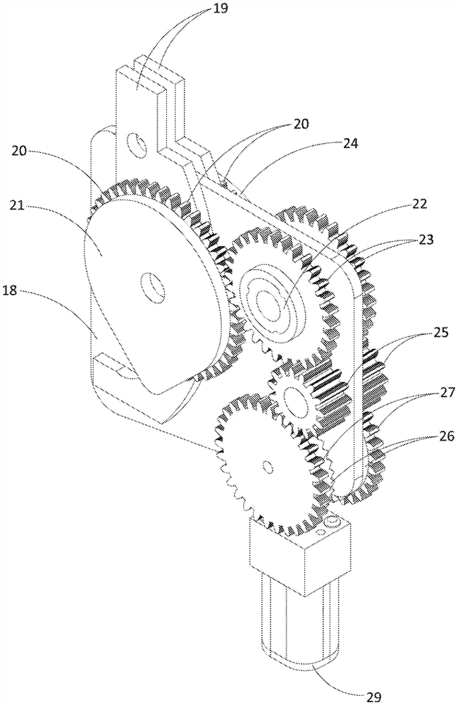
[0057] like figure 1As shown, 1. An electric locking mechanism, comprising a motor 29, two sets of mirror-symmetric transmission mechanisms and two mirror-symmetry output assemblies, the two sets of transmission mechanisms share one motor 29 for driving, and the transmission mechanisms will The kinetic energy of the motor 29 is transmitted to the output assembly; the output end of the motor 29 is provided with a drive gear 28, and the drive gear 28 is sleeved on the output shaft of the motor 29; the two groups of transmission mechanisms include input Gear 26, two described input gears 26 are face gears, and the rotating shafts of two described input gears 26 are parallel to each other; One described driving gear 28 meshes with two described input gears 26 respectively, two described input gears The gears 26 are spaced 180 degrees apart on the circumference where the drive gear 28 meshes.

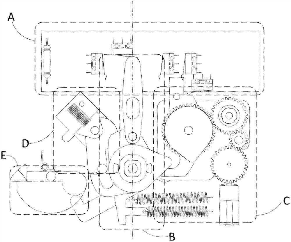
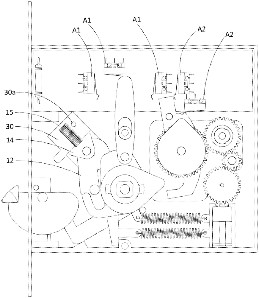
[0058] like Figure 2-Figure 13 As shown, a lock that does not distinguish between pub...

no. 2 example

[0106] In a further embodiment, such as Figure 16-25 As shown, in order to prevent the electronic lock system from being bypassed by items such as plastic cards and forcibly opening the door, on the basis of the foregoing embodiments, a first lock tongue synchronization member is provided on the side of the lock tongue 16 coaxially with the lock tongue rotation axis 163 and the second deadbolt synchronization member 164. Wherein, the second lock tongue synchronizing member 164 is disposed between the lock tongue 16 and the first lock tongue synchronizing member 163 . When the deadbolt 16 rotates along Z3 to lock the door, the second deadbolt synchronization member 164 is synchronized with the deadbolt 16 but extends outward in a straight line. In this embodiment, the limiting protrusion 1611 on the lock tongue 16 can be concave compared to the first embodiment, and its function is the same as that in the first embodiment, so it will not be repeated here. Due to the addition...


PUM


Abstract

An electric locking mechanism, comprising a motor (29), two sets of mirror-symmetric transmission mechanisms and two mirror-symmetry output assemblies, the two sets of transmission mechanisms are driven by a single motor (29), and the transmission mechanism transmits the kinetic energy of the motor (29) To the output assembly; the output end of the motor (29) is provided with a drive gear (28), and the drive gear sleeve (28) is on the output shaft of the motor (29); the two groups of transmission mechanisms all include an input gear (26), two input gears (26) are face gears, and the rotating shafts of two input gears (26) are parallel to each other, and the rotation direction of two input gears (26) is opposite; A driving gear (28) meshes with two input gears (26) respectively. The motor (29) drives the output of the output assembly through the transmission mechanism, and is driven by a motor (29), so the volume is smaller; on both sides of the door lock, when the transmission mechanism on one side is driven, the other side is not driven, realizing a single motor ( 29) Drivers for two unrelated systems.

Description

technical field [0001] The invention belongs to the field of locks, in particular to an electric locking mechanism. Background technique [0002] The existing electric lock has the following disadvantages: [0003] 1. The existing electric locks are bulky, and usually require the cooperation of multiple motors to complete the working process of the electric lock. [0004] 2. The control mode of the existing electric lock realizes the control through the positive and negative rotation of the motor, the control precision is low, and the reliability of the lock is not enough. [0005] 3. The motor has a single output on one plane, and the output on the plane is synchronized in real time, that is, the two planes interfere with each other. [0006] 4. When the motor outputs to the mechanism, the reaction of the mechanism can also allow the motor to rotate, which is greatly disturbed by the outside world, which is not conducive to the stable control of the lock. [0007] The ap...

Claims


Application Information

Patent Timeline
Patent Type & Authority Patents(China)
IPC IPC(8): E05B47/00
CPCE05B47/0669E05B47/0012E05B2047/0024E05B2047/002E05B65/0811E05B63/12E05B63/16E05B63/20E05B2047/0067E05B15/0086E05B15/0205E05B47/00E05Y2201/216E05Y2201/71E05Y2400/30E05B2047/0026E05Y2900/132
Inventor 庄培贤
Owner 岚间工作室有限公司
Why Eureka
Try Eureka