Eureka AIR delivers breakthrough ideas for toughest innovation challenges, trusted by R&D personnel around the world.

Punching forming equipment

A forming equipment and punching technology, applied in the field of stamping and forming dies, can solve the problems of low punching efficiency of punching equipment, and achieve the effects of improving service life, high efficiency and convenient replacement.

Inactive Publication Date: 2021-02-09
东莞中集专用车有限公司 +1
View PDF7 Cites 0 Cited by
  • Summary
  • Abstract
  • Description
  • Claims
  • Application Information

AI Technical Summary

Problems solved by technology

[0003] The purpose of the present invention is to provide a punching and forming equipment to solve the problem of low punching efficiency of punching equipment in the prior art

Method used


Image

  • Punching forming equipment
  • Punching forming equipment
  • Punching forming equipment

Examples


Embodiment Construction

[0028] Exemplary embodiments embodying the features and advantages of the present invention will be described in detail in the following description. It should be understood that the present invention can have various changes in different embodiments without departing from the scope of the present invention, and the descriptions and drawings therein are essentially used for illustration rather than limitation this invention.

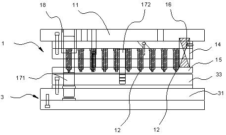
[0029] The present embodiment provides a punching and forming equipment, by using a combined punch structure, the pre-punching and punching forming can be completed at one time, thereby improving the production efficiency.

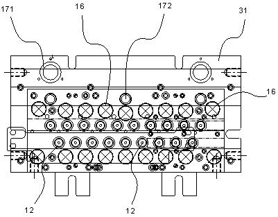
[0030] Please refer to figure 1 and figure 2 , the punching and forming equipment provided in this embodiment mainly includes an upper die assembly 1 and a lower die assembly 3 .

[0031] The punching and forming equipment is installed on the punching machine. In use, the upper die assembly 1 and the lower die assembly 3 are res...


PUM


Abstract

The invention provides punching forming equipment. The punching forming equipment comprises a lower die assembly and an upper die assembly which are oppositely arranged; the lower die assembly comprises a lower die base and a female die arranged above the lower die base; a groove and a blanking hole which is located below the groove and communicates with the groove are formed in the female die ina concave mode; the upper die assembly comprises an upper die base and a punching unit installed below the upper die base; the punching unit comprises a punching sleeve and a punching needle; a vertically-through accommodating cavity is formed in the center of the punching sleeve; a concave punching part is arranged on the periphery of the lower end of the punching sleeve; the section outline of the punching part is in an arc shape; the punching sleeve is opposite to the groove and performs punching through the punching part; the punching needle is accommodated in the accommodating cavity; thelower end of the punching needle extends downwards out of the accommodating cavity, is opposite to the blanking hole and is used for pre-punching; and the punching needle and the punching sleeve perform pre-punching and punching forming on a plate placed on the female die along with descending of the upper die base. By means of the combined punch unit, pre-punching and convex-punching forming canbe completed at a time, so that the production efficiency is improved.

Description

technical field [0001] The invention relates to the technical field of stamping and forming dies, in particular to a punching and forming equipment. Background technique [0002] In the vehicle manufacturing industry, the processing of holes on some auto parts, such as the anti-skid holes of automobile bumpers, is generally formed by stamping. At present, the forming method of the anti-skid hole is divided into two processes: pre-punching and punching, that is to say, two sets of dies need to be used for punching. First, a set of dies is used to punch the pre-punching on the sheet, and a pre-punching hole for positioning is punched on the sheet; then, another set of dies is used to punch the semi-finished sheet, and finally a non-slip hole is formed. Since the above punching method needs to be punched twice, the production efficiency is low. SUMMARY OF THE INVENTION [0003] The purpose of the present invention is to provide a punching and forming equipment to solve the ...

Claims


Application Information

Patent Timeline
Patent Type & Authority Applications(China)
IPC IPC(8): B26F1/02B26F1/14B26D7/26
CPCB26D7/2614B26F1/02B26F1/14
Inventor 李康民高承文张云巍刘克文夏勇
Owner 东莞中集专用车有限公司
Why Eureka
Eureka Blog
Learn More