Surface napping machine for concrete prefabricated part

A technology for concrete prefabricated parts and a hair pulling machine, which is applied to manufacturing tools, ceramic molding machines, etc., can solve the problems such as the inability to quickly adjust the pulling depth and the complex structure.

Inactive Publication Date: 2021-02-09
诸暨市壹格装修有限公司
View PDF1 Cites 2 Cited by
  • Summary
  • Abstract
  • Description
  • Claims
  • Application Information

AI Technical Summary

Problems solved by technology

Chinese patent (publication number: CN109159265A) discloses a napping machine for concrete prefabricated parts, which is characterized in that it includes: a support stand, the top of which has a longitudinal guide rail arranged along its length; on the top of the support stand, and can move back and forth and lock on the longitudinal moving guide rail, the top of the longitudinal moving trolley has a transverse moving guide rail arranged along its length; the transverse moving trolley is set on the longitudinal moving trolley, and can Move back and forth along the traversing guide rail and lock; the lifting mechanism includes a fixed frame vertically fixed below the traversing trolley and a mobile frame slidingly matched with the fixed frame. The mobile frame can move up and down along the fixed frame by means of a driving structure, although Under certain circumstances, this device can achieve a rapid napping effect on concrete prefabricated parts, but in actual operation, the device has a complex structure, and it cannot quickly adjust the napping depth of prefabricated parts with different thicknesses. Therefore, further research is still needed. improvement of

Method used


Image

  • Surface napping machine for concrete prefabricated part
  • Surface napping machine for concrete prefabricated part
  • Surface napping machine for concrete prefabricated part

Examples


Embodiment 1

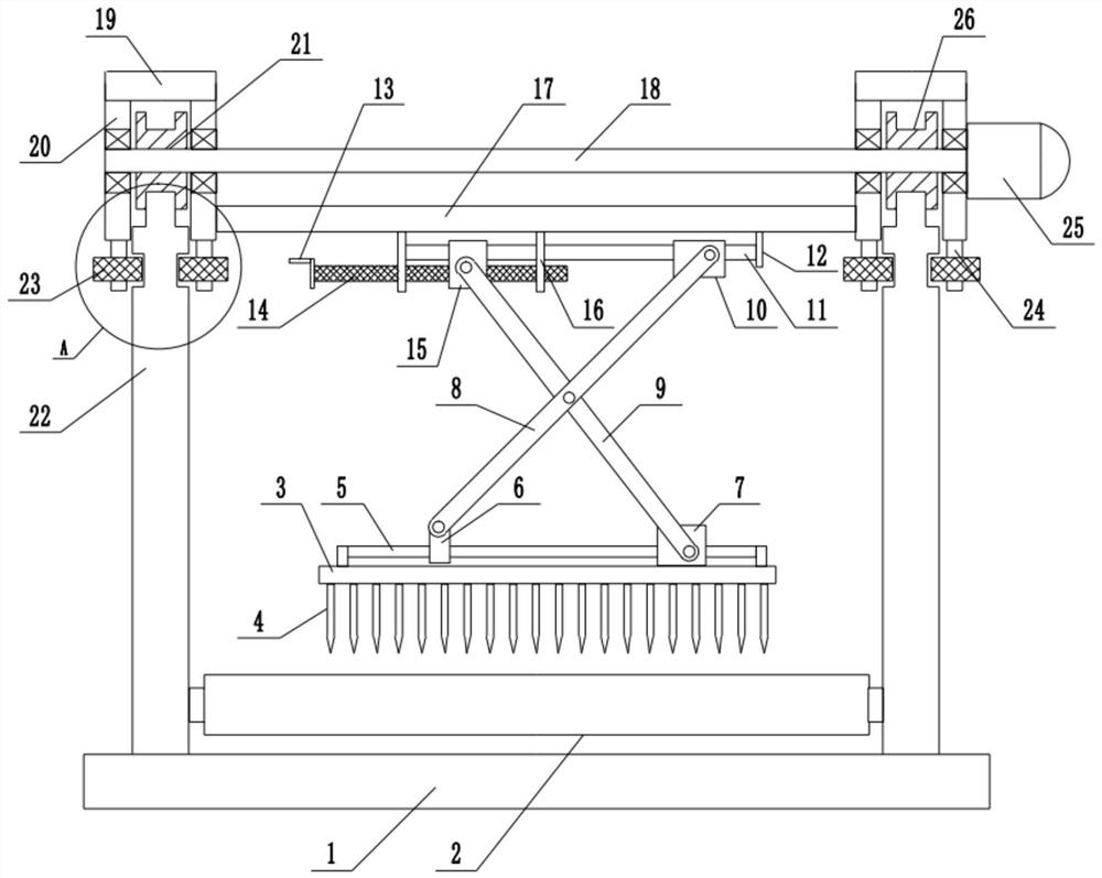
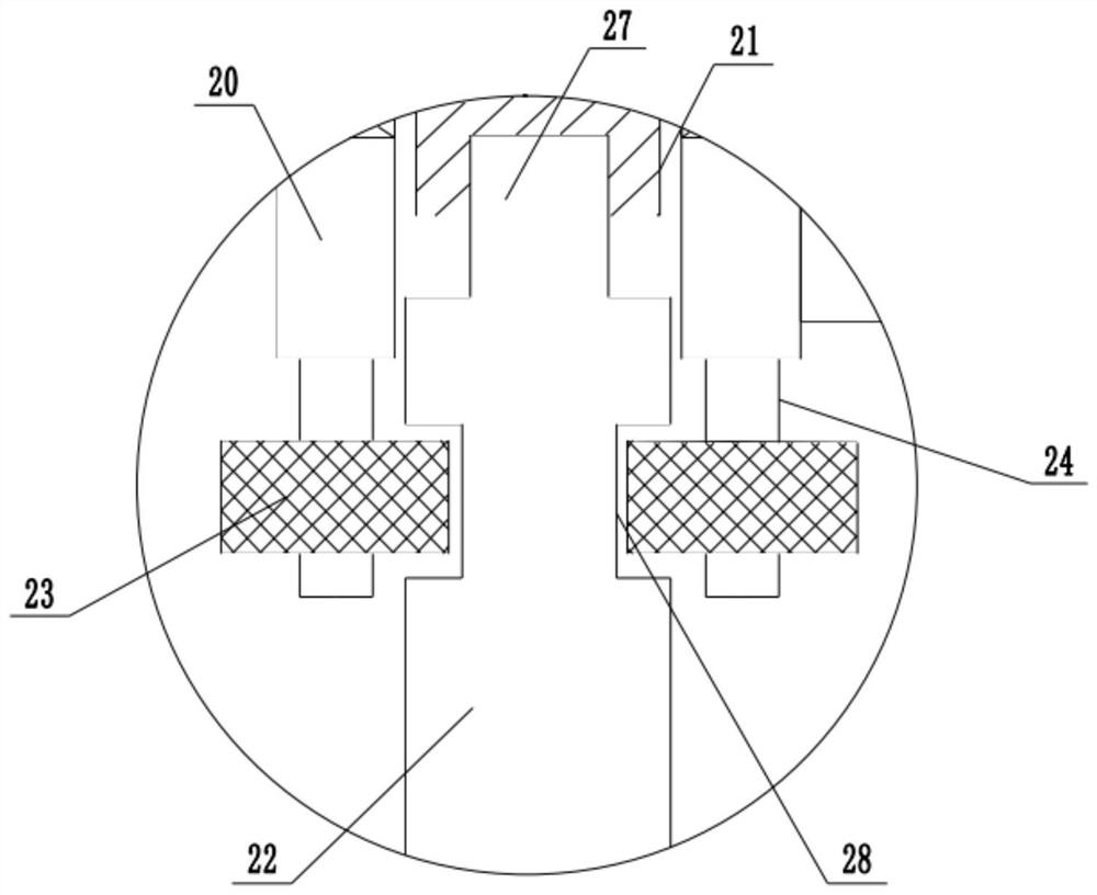
[0028] refer to Figure 1~3 , in an embodiment of the present invention, a surface roughening machine for concrete prefabricated parts, including a fixed base 1, fixed guide rails 22 are installed on both sides of the upper end of the fixed base 1, and walking roller groups 2 are installed between the bottoms of the fixed guide rails 22 , used to realize the effective transmission of concrete prefabricated parts, the top of the fixed guide rail 22 is slidably provided with a roller 21, thereby ensuring the forward and backward movement and conveyance at the top of the fixed guide rail 22, the outer side of the roller 21 is provided with a rolling groove 26, fixed The top of the guide rail 22 is provided with a raceway 27 that cooperates with the rolling groove 26. The setting of the raceway 27 and the rolling groove 26 can better ensure that the roller 21 will not shake left and right during the forward and backward movement, further increasing the moving effect A connecting s...

Embodiment 2

[0031]In another embodiment of the present invention, a fixed base 1 is included, fixed guide rails 22 are installed on both sides of the upper end of the fixed base 1 , walking roller sets 2 are installed between the bottoms of the fixed guide rails 22 , and rollers are slidingly provided on the top of the fixed guide rails 22 21, the outside of the roller 21 is provided with a rolling groove 26, the top of the fixed guide rail 22 is provided with a raceway 27 that cooperates with the rolling groove 26, and a connecting shaft 18 is installed between the middle parts of the roller 21, and the connecting shaft 18 is provided with a bearing through the rotation of the bearing. Walking plate 20, and connecting shaft 18 is fixedly connected with roller 21, and described connecting shaft 18 one ends are installed drive motor 25, and described driving motor 25 is double steering stepper motor, and driving motor 25 is fixed on the walking plate 20, and described roller Walking board 2...


PUM


Abstract

The invention relates to the technical field of concrete prefabricated part machining equipment, and discloses a surface napping machine for a concrete prefabricated part. The surface napping machinecomprises a fixed base, wherein fixed guide rails are installed on the two sides of the upper end of the fixed base; rolling wheels are arranged at the top ends of the fixed guide rails in a sliding mode; connecting shafts are installed between the middles of the rolling wheels; walking plates are installed on the connecting shafts at the two ends of the rolling wheels respectively; a top plate isinstalled at the top ends of the walking plates; a walking frame is installed between the walking plates on the inner side; an upper guide frame is installed at the lower end of the walking frame; afirst guide block is arranged on the left side of the upper guide frame in a sliding mode; the lower end of the first guide block is connected with a stud through a threaded structure; a second guideblock is arranged at the right end of the upper guide frame in a sliding mode; a first connecting rod is hinged to the first guide block; and a second connecting rod is hinged to the second guide block. According to the surface napping machine, the whole device can move front and back along the fixed guide rails, the movement requirement of napping is met, the adjustment of the vertical height ofa napping plate is ensured, and the napping requirements of different depths of concrete prefabricated parts with different thicknesses are met.

Description

technical field [0001] The invention relates to the technical field of concrete prefabricated parts processing equipment, in particular to a surface roughening machine for concrete prefabricated parts. Background technique [0002] Concrete precast parts, also known as PC components, refer to concrete products that are processed and produced in factories through standardized and mechanized methods. Correspondingly, traditional cast-in-place concrete requires on-site molding, on-site pouring and on-site maintenance. Prefabricated concrete is widely used in construction, transportation, water conservancy and other fields, and plays an important role in the national economy. [0003] In the construction industry, the roughening equipment is an important part of the auxiliary equipment of the concrete prefabricated component production line. The roughening machine is used to draw a straight line texture with a certain depth and width on the surface of the initially set prefabri...

Claims


Application Information

Patent Timeline
Patent Type & Authority Applications(China)
IPC IPC(8): B28B11/08
CPCB28B11/0818
Inventor 周狄超
Owner 诸暨市壹格装修有限公司
Why Eureka
Try Eureka