Wire conveying structure for mural masonry stripping equipment

A technology of stripping equipment and wire transportation, which is used in stone processing equipment, transportation of filamentous materials, transportation and packaging, etc., can solve problems such as high experience and physical strength requirements, large manual operation errors, and damage to murals. Vibration, guaranteed cutting efficiency, and the effect of small moment of inertia

Pending Publication Date: 2021-02-09
SHAANXI HISTORY MUSEUM +1
View PDF0 Cites 0 Cited by
  • Summary
  • Abstract
  • Description
  • Claims
  • Application Information

AI Technical Summary

Problems solved by technology

How to completely extract the precious murals from the tomb passage is a big challenge for cultural relics personnel. At present, murals are usually cut into pieces manually, otherwise they will be broken. This determines the time when the murals are cut. There will inevitably be damage, resulting in irreparable consequences, and the manual operation error is large, which requires relatively high experience and physical strength, and manual cutting is bound to damage the mural
[0003] So far, there is no automatic or semi-automatic equipment applied to the mural stripping industry for reference. For the mural industry, it is a brand-new technical blank. It can only be calculated and designed step by step through a lot of trials, tests, and verifications; according to the cutting medium Analysis and selection of combined cutting and peeling methods based on the characteristics of the mixture, structure, and connection between them;

Method used


Image

  • Wire conveying structure for mural masonry stripping equipment
  • Wire conveying structure for mural masonry stripping equipment

Examples


specific Embodiment approach

[0026] It should be noted that the structures, proportions, sizes, etc. shown in this specification are only used to cooperate with the content disclosed in the specification for the understanding and reading of those familiar with this technology, and are not used to limit the conditions for the implementation of the present invention , any modification of structure, change of proportional relationship or adjustment of size shall still fall within the scope covered by the technical content disclosed in the present invention without affecting the effect and purpose of the present invention. .

[0027] At the same time, terms such as "upper", "lower", "left", "right", "middle" and "one" quoted in this specification are only for the convenience of description and are not used to limit this specification. The practicable scope of the invention and the change or adjustment of its relative relationship shall also be regarded as the practicable scope of the present invention without...


PUM


Abstract

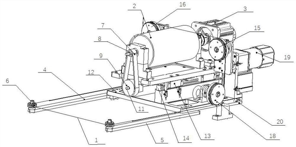
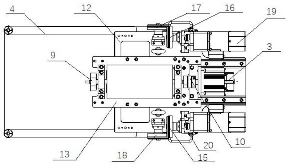
The invention discloses a wire conveying structure for mural masonry stripping equipment. The wire conveying structure comprises a wire rotating assembly, a wire guide wheel assembly and a wire cutting assembly. The wire rotating assembly comprises a front-back shifting component, a wire, a wire conveying shaft and a wire conveying servo motor. The wire cutting assembly comprises a first rod piece, a second rod piece and wire guide wheels, wherein the first rod piece and the second rod piece are arranged in parallel. The wire conveying shaft is mounted on the front-back shifting component. Oneend of the wire conveying shaft is connected with the wire conveying servo motor. The wire is wound on a wire shaft. One end of the first rod piece and one end of the second rod piece are both connected to the bottom of the front-back shifting component, and the other end of the first rod piece and the other end of the second rod piece are both provided with the wire guide wheels. The wire is wound on the wire conveying shaft, and one end of the wire extends out of the wire conveying shaft and forms a wire winding path through the wire guide wheel assembly and the two wire guide wheels. The wire conveying structure for the mural masonry stripping equipment is designed and used for equipment for cutting mural masonries in cultural relic excavation, complete cutting is achieved through reciprocating motion of the wire, and damage to murals due to vibration, noise and use of cooling liquid is reduced.

Description

technical field [0001] The invention belongs to the technical field of cultural relic mural cutting equipment, and in particular relates to a wire transporting structure for mural masonry stripping equipment. Background technique [0002] Ancient murals refer to paintings drawn directly on walls by people. They usually appear on the walls of grottoes, tombs or important buildings. They are important materials reflecting ancient society, life, art, etc., and are also witnesses of ancient Chinese civilization. Here mainly refers to paintings drawn by painters in ancient tombs with certain historical and archaeological value or on surfaces such as rocks. Exquisite murals generally come from noble tombs. However, there are a lot of soil, water and microorganisms in ancient tombs. Destructive effect on murals. How to completely extract the precious murals from the tomb passage is a big challenge for cultural relics personnel. At present, murals are usually cut into pieces manual...

Claims


Application Information

Patent Timeline
Patent Type & Authority Applications(China)
IPC IPC(8): B65H59/10B28D1/22
CPCB28D1/22B65H59/10
Inventor 杨文宗王佳谢昆金紫琳
Owner SHAANXI HISTORY MUSEUM
Why Eureka
Try Eureka