A papermaking dryer mechanism

A papermaking dryer and drying cylinder technology, applied in the papermaking field, can solve the problems of high production cost, unsteady transmission of the paper web, and difficulty in grasping the paper tension, so as to reduce equipment maintenance costs, reduce poor tension control, and improve energy The effect of utilization efficiency

Active Publication Date: 2022-08-05
DONGGUAN JINTIAN PAPER CO LTD
View PDF8 Cites 0 Cited by
  • Summary
  • Abstract
  • Description
  • Claims
  • Application Information

AI Technical Summary

Problems solved by technology

[0003] Because there will be certain errors in the specifications of each drying cylinder in the drying cylinder device, there will be a speed difference between the drying cylinders and the drying cylinders when they rotate, which will cause the paper web to not be driven smoothly, and the tension of the paper cannot be well adjusted. Thus affecting the quality of paper production
On the other hand, when the drying cylinder device needs to slow down or shut down, it is even more difficult for the operator to grasp the tension of the paper, and the situation of paper breakage or warping occurs frequently
In the prior art, there are very few processes that equip the drying device with a brake device, which can achieve a relatively uniform deceleration effect. However, the existing brake device is relatively primitive, and the sensitivity to tension control is low, and there are still problems with product quality. Influenced by the influence, it is still easy to cause paper breakage, and the paper will be warped and deformed due to the large change of tension, and the paper damage rate remains high
The old-fashioned brake device is noisy, and the noise of the power-on detection is as high as 90-100Db, which makes the working environment of the employees worse. Moreover, the brake pads of this type of brake device wear out quickly, and the service life is 15-20 days, and the production cost is high.

Method used


Image

  • A papermaking dryer mechanism
  • A papermaking dryer mechanism
  • A papermaking dryer mechanism

Examples


Embodiment Construction

[0041] The technical solutions in the embodiments of the present invention will be clearly and completely described below with reference to the accompanying drawings of the present invention. Obviously, the described embodiments are only a part of the embodiments of the present invention, rather than all the embodiments. Based on the embodiments of the present invention, all other embodiments obtained by those of ordinary skill in the art without creative work fall within the protection scope of the present invention.

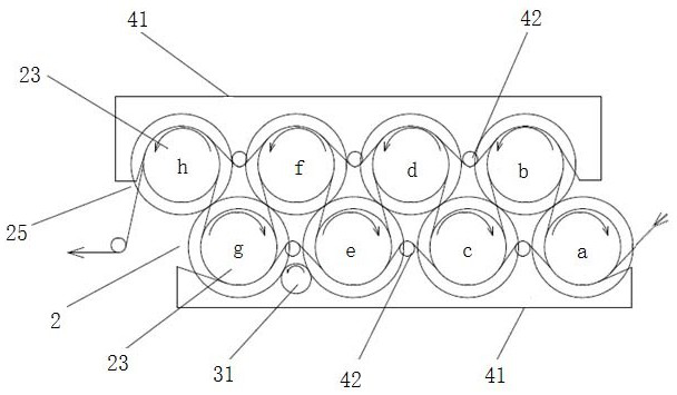
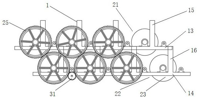
[0042] A papermaking dryer mechanism according to an embodiment of the present invention, such as figure 1 and image 3 As shown, it includes a frame 1, several drying cylinder assemblies 2 installed on the frame 1, a driving assembly 3 connected to any drying cylinder assembly 2 in a driving manner, a supporting assembly 4 installed on the overall periphery of the drying cylinder assembly 2, and the brake assembly 5 mounted on the drive assembly 3, wherein:

...


PUM


Abstract

The invention relates to the technical field of papermaking, and specifically discloses a papermaking drying cylinder mechanism. The papermaking drying cylinder mechanism comprises a frame, a plurality of drying cylinder assemblies installed on the frame, and a driving assembly drivingly connected with any drying cylinder assembly. A supporting assembly on the entire periphery of the dryer assembly, and a brake assembly installed on the drive assembly, wherein: the dryer assembly includes an upper dryer assembly and a lower dryer assembly that are disposed up and down staggered; the upper dryer assembly and the lower dryer assembly Both include a drying cylinder body, a central shaft axially penetrating the drying cylinder body, and a transmission gear installed at the front end of the central shaft; the drive assembly includes a motor, a drive shaft fixedly connected to the output end of the motor, and an active drive fixedly connected to the other end of the drive shaft. The gear, the driving gear meshes with any transmission gear for transmission; the brake assembly is sleeved on the drive shaft. The papermaking drying cylinder mechanism of the invention can dry the paper web and make the conveying smoothly, can better adjust the tension of the paper, and improve the production quality of the paper.

Description

technical field [0001] The invention relates to the technical field of papermaking, in particular to a drying cylinder mechanism for papermaking. Background technique [0002] The papermaking process usually includes a series of treatments such as forming, pressing, pre-drying, sizing / coating (surface treatment) post-drying, calendering, and rolling. In the drying stage after pressing and dehydration or sizing coating, the existing drying device generally consists of a plurality of drying cylinders, each of which is driven by a different motor to drive the paper, thereby drying the paper. [0003] Due to certain errors in the specifications of each drying cylinder in the drying cylinder device, a speed difference occurs between the drying cylinder and the drying cylinder during rotation, which in turn leads to the inability of the paper web to be driven smoothly and the tension of the paper to be adjusted well. Thus affecting the quality of paper production. On the other h...

Claims


Application Information

Patent Timeline
Patent Type & Authority Patents(China)
IPC IPC(8): D21F5/04D21F5/02D21F7/02
CPCD21F5/04D21F5/021D21F5/02D21F7/02
Inventor 袁毅甘延文张建杨琪林
Owner DONGGUAN JINTIAN PAPER CO LTD
Why Eureka
Try Eureka