
Induction furnace

A technology of induction furnace and furnace body, applied in the field of induction furnace, can solve problems such as time-consuming

Pending Publication Date: 2021-02-09
FUJI ELECTRIC CO LTD
View PDF9 Cites 0 Cited by
  • Summary
  • Abstract
  • Description
  • Claims
  • Application Information

AI Technical Summary

Problems solved by technology

Therefore, in the yoke of Patent Document 1, it is difficult to stack a plurality of plates with different shapes and angles to form an annular shape, and it requires time-consuming work. In addition, gaps are likely to be generated between the stacked plates. However, partial discharges are generated at the ends of each plate, etc.

Method used


Image

  • Induction furnace
  • Induction furnace
  • Induction furnace

Examples


Embodiment Construction

[0021] Hereinafter, an induction furnace according to an embodiment of the present invention will be described in detail with reference to the drawings. In addition, this invention is not limited to the following embodiment, In the range which does not change the summary, it can deform suitably and implement. In the following drawings, some structures may be omitted for convenience of description.

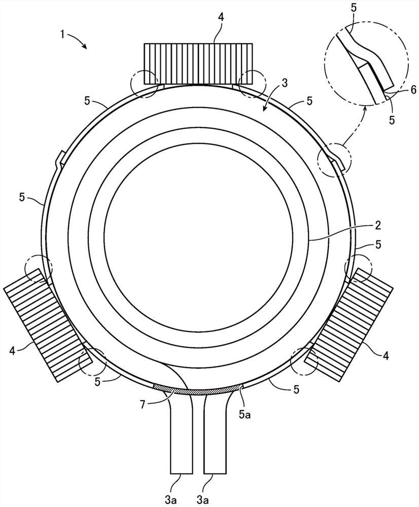
[0022] figure 1 It is a schematic plan view of the induction furnace of embodiment. Such as figure 1 As shown, the induction furnace 1 includes: a bottomed vessel-shaped furnace body 2 with an open top and a cylindrical peripheral wall; and a coil 3 wound around the outer peripheral side of the peripheral wall of the furnace body 2 .

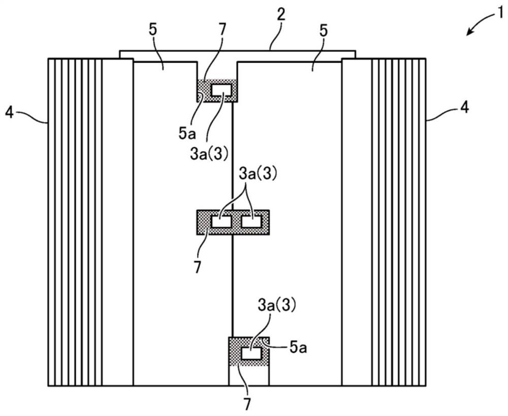
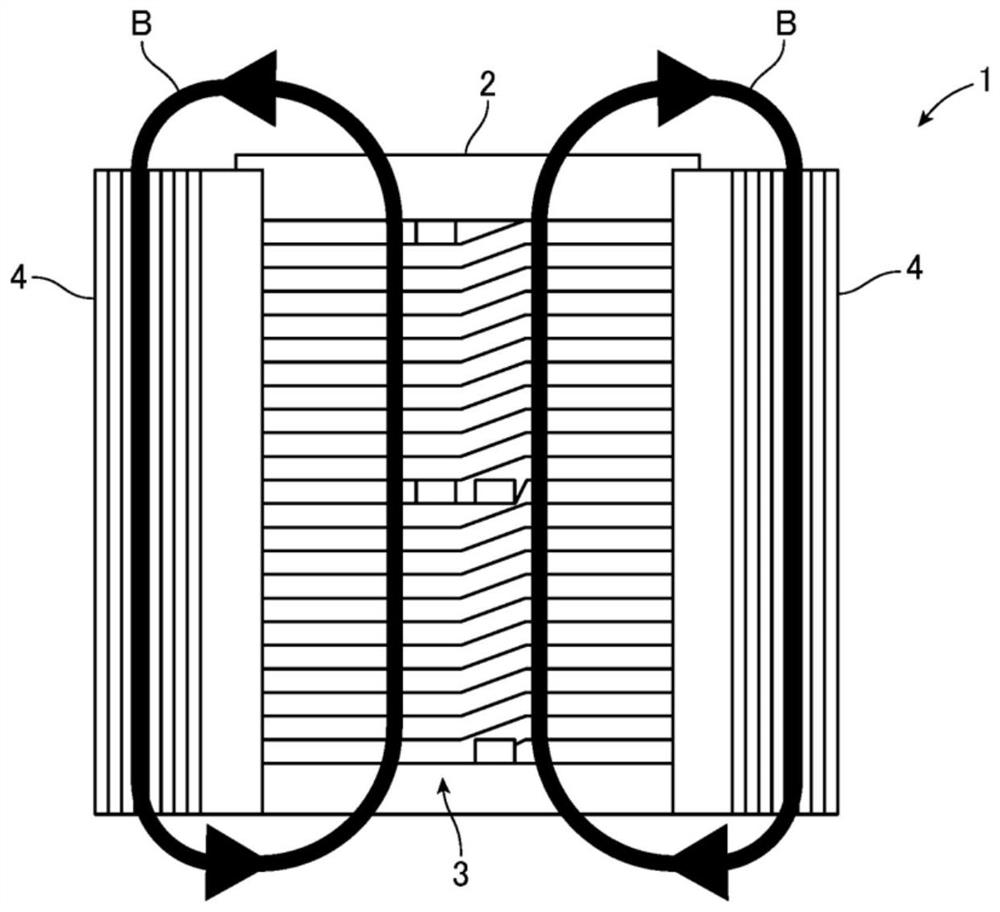
[0023] The furnace body 2 is made of a refractory material or the like, and a material to be melted such as iron scrap is charged into the furnace body 2 to be melted. The coil 3 is disposed concentrically with the furnace body 2, and the end 3...


PUM


Abstract

The invention provides an induction furnace. The induction furnace can alleviate electric field concentration of a yoke and can apply high voltage to a coil. An induction furnace (1) comprises: a coil(3) provided on the outer peripheral side of a furnace body (2); a plurality of yokes (4) provided on the outer peripheral side of the coil (3) at predetermined intervals in the circumferential direction of the coil; and a conductive member (5) provided at a position surrounding the outer peripheral side of the coil. The conductive member is formed of a thin member along the outer periphery of the coil. The yoke and the conductive member are electrically connected to have the same potential, thereby suppressing concentration of an electric field generated by the surface of the coil at the endof the yoke and uniformly generating the electric field along the surface of the conductive member. Consequently, electric field concentration at the end of the yoke can be mitigated.

Description

technical field [0001] The invention relates to an induction furnace, in particular to a yoke-type induction furnace provided with a plurality of yokes outside a coil. Background technique [0002] An induction furnace disclosed in Patent Document 1 is known as an induction furnace for melting scrap iron or the like. The induction furnace of Patent Document 1 includes a heating coil provided on the outer periphery of a crucible, and a yoke (yoke) provided to cover the outer periphery of the coil. [0003] In the induction furnace of Patent Document 1, the yoke is formed into a wedge shape by arranging and bonding thicker plates and thinner plates shorter in size than the thicker plates, and the wedge-shaped plates are arranged alternately. and formed into a circular shape. Therefore, in the yoke of Patent Document 1, it is difficult to stack a plurality of plates with different shapes and angles to form an annular shape, and it requires time-consuming work. In addition, ga...

Claims


Application Information

Patent Timeline
Patent Type & Authority Applications(China)
IPC IPC(8): F27B14/06F27B14/08F27B14/14F27B14/20F27D11/06
CPCF27B14/061F27B14/14F27B14/20F27B14/08F27D11/06
Inventor 早瀬悠二
Owner FUJI ELECTRIC CO LTD
Learn More