
Vertical fish killing device

A fish slaughtering and vertical technology, which is applied in the direction of slaughtering, processing fish, fish cleaning / descaling, etc., can solve the problems of high labor intensity, low work efficiency, high cost, etc., and achieve improved efficiency, low labor intensity and high work efficiency Effect

Inactive Publication Date: 2021-02-12
利辛县子恒食品加工厂
View PDF8 Cites 3 Cited by
  • Summary
  • Abstract
  • Description
  • Claims
  • Application Information

AI Technical Summary

Problems solved by technology

[0002] At present, in the food processing industry, the operation of digging out the viscera after slaughtering fish is also included. At present, most of the methods for removing the viscera of fish still adopt the method of manually dissecting the fish abdomen. Use scissors or cutting blades to cut fish one by one. Because the mucus secreted by the fish itself is very slippery, manual cutting is not easy to handle. Moreover, this method has low work efficiency and high labor intensity, requiring a lot of manpower. , the cost of production and processing is high, and it cannot adapt to the development needs of the food processing industry, so a vertical fish slaughtering device is designed here to solve the above problems

Method used


Image

  • Vertical fish killing device
  • Vertical fish killing device
  • Vertical fish killing device

Examples


Embodiment 1

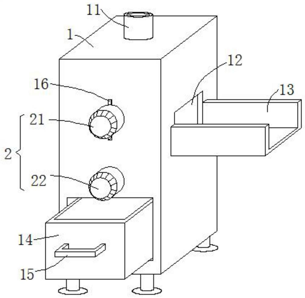
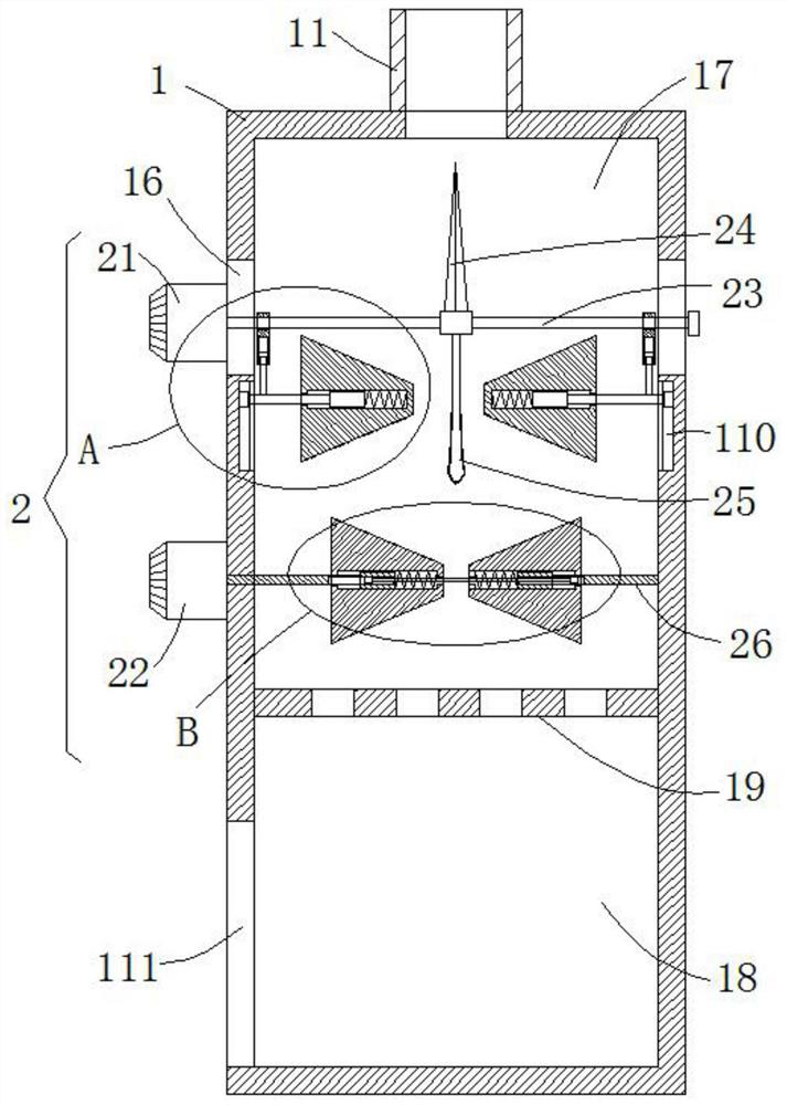
[0024] see Figure 1-4 , this embodiment provides a vertical fish slaughtering device, comprising a cabinet body 1, one side of the cabinet body 1 is provided with a feed port, and the other side is provided with a discharge port 12, and the discharge port 12 is horizontally provided with The receiving plate 13, in order to complete the slaughtering operation, it is necessary to put the fish to be slaughtered into the cabinet 1 through the feeding port, and the slaughtered fish is discharged through the discharging port 12 and falls on the receiving plate 13, which is convenient for centralized collection operation ;

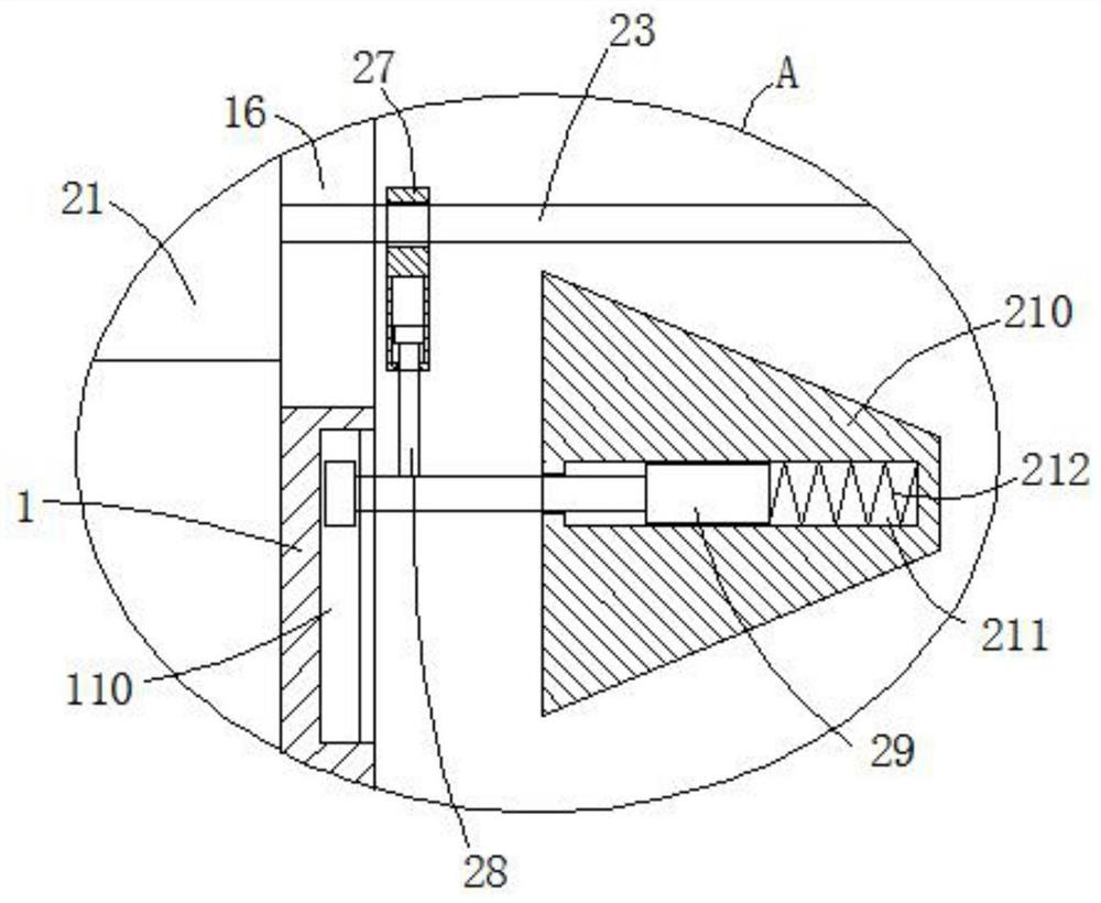
[0025] In order to solve the problem of how to dissect the fish body, the interior of the cabinet 1 is a hollow structure, and is divided into an operation chamber 17 and a recovery chamber 18 by a filter plate 19 having a discharge hole. The operating mechanism 2 of the fish, the operating chamber 17 is used as the place where the operating mechanism 2 slaught...

Embodiment 2

[0035] see figure 2 with Figure 4 , further improvements have been made on the basis of Example 1:

[0036] In order to solve the problem of the linkage of the two frustum-shaped transmission rollers 213, two T-shaped transmission rods 26 are provided with T-shaped transmission grooves 216 at the ends close to each other, and the side view structure of the T-shaped transmission grooves 216 is a rectangular structure. The I-shaped connecting rod 217 that runs through the two transmission holes 214 is slidably inserted between the T-shaped transmission grooves 216, and the I-shaped connecting rod 217 that can be driven is set between the two truncated cone-shaped transmission rollers 213, so that During one of them truncated cone type transmission roller 213, also can drive another truncated cone type transmission roller 213 to rotate in the same direction synchronously, be convenient to play the purpose of transmission to fish body.


PUM


Abstract

The invention discloses a vertical fish killing device, which relates to the technical field of food processing, and comprises a cabinet body, one side of the cabinet body is provided with a feed port, the other side of the cabinet body is provided with a discharge port, the discharge port is horizontally provided with a material receiving plate, the interior of the cabinet body is of a hollow structure, and the cabinet body is divided into an operation chamber and a recovery chamber through a filter plate provided with a discharge hole; and an operating mechanism for killing fishes is arranged in the operating chamber. The vertical fish killing device is convenient for assisting in quickly killing fishes in batches, is convenient for clamping fish bodies without sideslip in the killing process, is high in working efficiency and low in labor intensity, does not need to invest a large amount of manpower, and improves the benefits of food processing.

Description

technical field [0001] The invention relates to the technical field of food processing, in particular to a vertical fish slaughtering device. Background technique [0002] At present, in the food processing industry, the operation of digging out the viscera after slaughtering fish is also included. At present, most of the methods for removing the viscera of fish still adopt the method of manually dissecting the fish abdomen. Use scissors or cutting blades to cut fish one by one. Because the mucus secreted by the fish itself is very slippery, manual cutting is not easy to handle. Moreover, this method has low work efficiency and high labor intensity, requiring a lot of manpower. , the cost of production and processing is higher, and it cannot adapt to the development needs of the food processing industry, so a vertical fish slaughtering device is designed here to solve the above problems. Contents of the invention [0003] The object of the present invention is to provide ...

Claims


Application Information

Patent Timeline
Patent Type & Authority Applications(China)
IPC IPC(8): A22B3/08A22C25/08A22C25/14A22C25/02
CPCA22B3/08A22C25/02A22C25/08A22C25/145
Inventor 李浩张鹏
Owner 利辛县子恒食品加工厂
Learn More