
A multifunctional non-magnetic rotating bed

A multifunctional, bed frame technology, applied in the field of transfer beds, can solve problems such as damage to magnetic resonance imagers, aggravation of patients' conditions, and secondary injuries of patients

Active Publication Date: 2022-04-22
泰安仁和屏蔽防护工程有限公司
View PDF9 Cites 0 Cited by
  • Summary
  • Abstract
  • Description
  • Claims
  • Application Information

AI Technical Summary

Problems solved by technology

[0002] At present, the magnetic field strength of the magnetic resonance imager used in most hospitals is about 30,000 to 60,000 times that of the earth's magnetism; when this large magnet touches a ferromagnetic object in an unsafe range, the strong attraction of the magnet will It is attracted to the magnet, and the ferromagnetic object will be projected onto the magnet at high speed like a bullet, causing fatal damage to the MRI machine; therefore, the patient transfer device that can enter the MRI examination room must be made of non-magnetic materials , and because for patients with cardiovascular and cerebrovascular diseases, spinal injuries, bone trauma, and patients who need to undergo magnetic resonance examinations, relying on manual handling can easily cause secondary injuries to the patients and aggravate the patient's condition. In order to ensure the safety of examinations, it is urgent to develop a non-magnetic A transfer bed that can enter the MRI examination room and transport patients safely and smoothly

Method used


Image

  • A multifunctional non-magnetic rotating bed
  • A multifunctional non-magnetic rotating bed
  • A multifunctional non-magnetic rotating bed

Examples


Embodiment 1

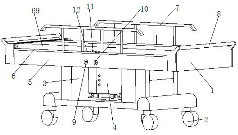
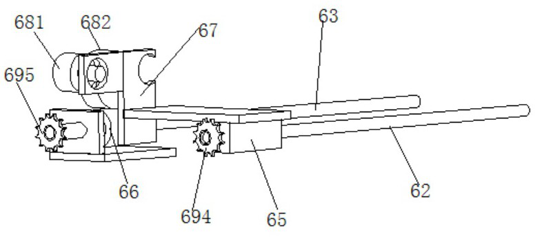
[0026] Such as Figure 1 to Figure 9 As shown, the multifunctional non-magnetic running bed includes a transfer car main body 1, and a universal silent wheel 2 installed at the bottom of the transfer car main body; and a lifting mechanism 3 and an electric drive module 4 fixed on the top surface of the transfer car main body; and a fixed The liftable platform 5 on the top surface of the lifting mechanism and the electric drive module; and the translation transmission belt mechanism 6 that is installed on the liftable platform and moves along the width direction of the liftable platform; Guardrail 7; And be arranged on the handle 8 of transfer car main body length two ends; And be arranged on the first manual drive interface 9 and the second manual drive interface 10 on the liftable platform, and with the first manual drive interface and the second hand drive interface The hand rocker that is movably plugged into the dynamic drive interface; and the control switch 12 that is ar...


PUM


Abstract

The invention discloses a multifunctional non-magnetic running bed, which comprises a main body of a transfer vehicle, a universal silent wheel installed at the bottom of the main body of the transfer vehicle; a lifting mechanism and an electric drive module fixed on the top surface of the main body of the transfer vehicle; The lifting mechanism and the liftable platform on the top surface of the electric drive module; and the translation transmission belt mechanism installed on the liftable platform and moving along the width direction of the liftable platform; and the self-locking guardrails installed on both sides of the liftable platform width; And the handles arranged at both ends of the main body of the transfer vehicle; and the first manual drive interface and the second manual drive interface arranged on the liftable platform, and the first manual drive interface and the second manual drive interface. The multi-functional non-magnetic operation bed of the present invention can realize the whole non-magnetic effect, and can be used as a special non-magnetic transfer bed for the magnetic resonance room. It has the functions of lifting, docking and automatic pick-up. Rocker drive.

Description

technical field [0001] The invention relates to a transfer bed, in particular to a multifunctional non-magnetic rotating bed, which belongs to the technical field of transfer beds. Background technique [0002] At present, the magnetic field strength of the magnetic resonance imager used in most hospitals is about 30,000 to 60,000 times that of the earth's magnetism; when this large magnet touches a ferromagnetic object in an unsafe range, the strong attraction of the magnet will It is attracted to the magnet, and the ferromagnetic object will be projected onto the magnet at high speed like a bullet, causing fatal damage to the MRI machine; therefore, the patient transfer device that can enter the MRI examination room must be made of non-magnetic materials , and because for patients with cardiovascular and cerebrovascular diseases, spinal injuries, bone trauma, and patients who need to undergo magnetic resonance examinations, relying on manual handling can easily cause secon...

Claims


Application Information

Patent Timeline
Patent Type & Authority Patents(China)
IPC IPC(8): A61G1/02A61G1/04
CPCA61G1/02A61G1/04A61G2203/10A61G2210/00
Inventor 孙文峰
Owner 泰安仁和屏蔽防护工程有限公司
Learn More