Twin-roll cast-rolling device for aluminum alloy clean production and deep processing

A clean production, aluminum alloy technology, applied in the field of twin-roll casting and rolling equipment, to achieve the effect of preventing corrosion

Inactive Publication Date: 2021-02-12
方新全
View PDF9 Cites 3 Cited by
  • Summary
  • Abstract
  • Description
  • Claims
  • Application Information

AI Technical Summary

Problems solved by technology

This limits the arbitrary adjustment of the roll gap of the casting and rolling mill from the two aspects of process and equipment

Method used


Image

  • Twin-roll cast-rolling device for aluminum alloy clean production and deep processing
  • Twin-roll cast-rolling device for aluminum alloy clean production and deep processing
  • Twin-roll cast-rolling device for aluminum alloy clean production and deep processing

Examples


Embodiment 1

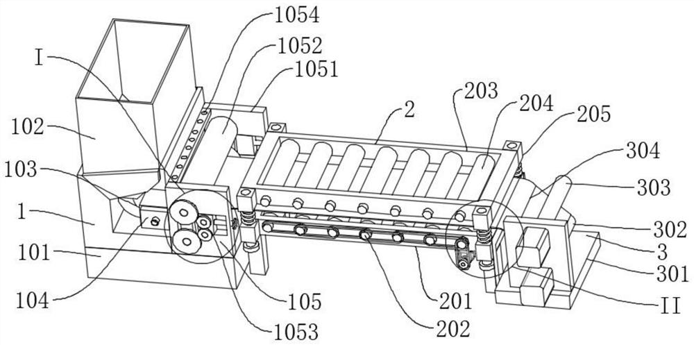
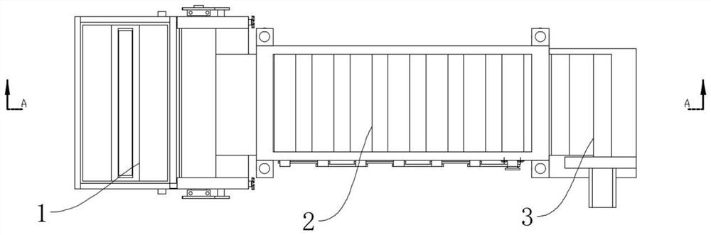
[0033] Such as Figure 1-Figure 7 As shown, a twin-roll casting and rolling device for clean production and deep processing of aluminum alloys includes an oil absorbing mechanism 2, a traction and winding mechanism 3, and a casting and rolling mechanism 1. An oil absorbing mechanism 2 is arranged on one side of the casting and rolling mechanism 1, and the oil absorbing mechanism 2. A traction and winding mechanism 3 is provided on the side away from the casting and rolling mechanism 1. The casting and rolling mechanism 1 includes a supporting platform 101, a tundish 102, a blanking mold 103, a cooling assembly 104, and a forming assembly 105. The top of the supporting platform 101 is connected by bolts. There is a tundish 102, the bottom of the tundish 102 is connected with a blanking mold 103 by bolts, the outer side of the blanking mold 103 is provided with a cooling assembly 104, and the outlet of the blanking mold 103 is provided with a molding assembly 105, so that the ins...

Embodiment 2

[0035] Such as Figure 8 As shown, the difference between embodiment 2 and embodiment 1 is that: the end of the pulling plate 304 away from the pulling roller 302 is welded with a hanging plate 3042, which can effectively pull the solidified aluminum alloy plate.

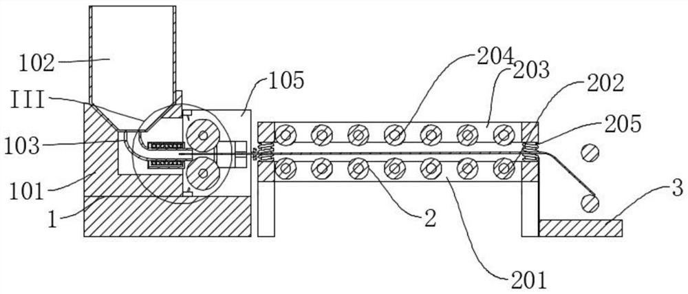
[0036] In the above structure, when in use, the ejector rod 2053 is first lifted, and the ejector rod 2053 drives the upper fixing block 2052 to rise, thereby causing the fixing frame 203 to rise, so that the distance between the pressure roller 204 and the idler roller 202 becomes larger, and then the traction plate is pulled 304, so that one end of the traction plate 304 passes between the forming rollers 1052 and stretches into the inside of the blanking mold 103, and then releases the ejector pin 2053, so that the pressure roller 204 is pressed down on the traction plate 304, and then the liquid in the tundish 102 is It flows into the blanking mold 103, and the cooling assembly 104 is connected to the water sour...


PUM


Abstract

The invention discloses a twin-roll cast-rolling device for aluminum alloy clean production and deep processing. The twin-roll cast-rolling device comprises an oil absorption mechanism and a tractionwinding mechanism, and further comprises a cast-rolling mechanism, wherein the oil absorption mechanism is arranged on one side of the cast-rolling mechanism, and the traction winding mechanism is arranged on the side, far away from the cast-rolling mechanism, of the oil absorption mechanism; and the cast-rolling mechanism comprises a supporting table, a tundish, a discharging die, a cooling assembly and a forming assembly, and the tundish is connected to the top of the supporting table through bolts. According to the twin-roll cast-rolling device for aluminum alloy clean production and deep processing, the cooling assembly absorbs heat of liquid inside the discharging die, so that the liquid is solidified inside the discharging die, even a gap exists between the discharging die and a forming roller, normal production is not affected, and the function of adjusting the production thickness of aluminum alloy plates is also achieved; and through the arrangement of an oil spraying assembly, the situation that the production quality is affected due to the phenomenon of roll sticking on the surface of the forming roller is avoided, and the aluminum alloy plates can also be prevented frombeing corroded during later storage.

Description

technical field [0001] The invention relates to the technical field of clean production of aluminum alloys, in particular to a twin-roll casting and rolling device for clean production and deep processing of aluminum alloys. Background technique [0002] In the continuous casting and rolling production of aluminum and aluminum alloy slabs, the roll gap is an important process parameter, which determines the thickness of the cast slab. However, the roll gap cannot be adjusted arbitrarily since the birth of the twin-roll casting machine. During the rolling process, the installation position of the feeding nozzle and the size of the roll gap can only be adjusted slightly. Increasing the roll gap can increase the thickness of the plate, and at the same time, the gap between the roll nozzles will also increase. When the gap between the roll nozzles reaches a certain level and exceeds the surface tension limit of the aluminum liquid, aluminum water will flow out from the gap betwe...

Claims


Application Information

Patent Timeline
Patent Type & Authority Applications(China)
IPC IPC(8): B22D11/06
CPCB22D11/0622
Inventor 方新全周慧慧
Owner 方新全
Why Eureka
Try Eureka