
Intelligent metal cutting machine tool for automobile part production

A metal cutting and spare parts technology, applied in the field of intelligent metal cutting machine tools, can solve the problems of wear of cutting blades, easy spark sputtering in cutting, and reduced durability of cutting blades, so as to achieve safe cutting process, avoid inconvenient adjustment and operation, The effect of avoiding wear

Inactive Publication Date: 2021-02-12
广州承光电子科技有限公司
View PDF7 Cites 0 Cited by
  • Summary
  • Abstract
  • Description
  • Claims
  • Application Information

AI Technical Summary

Problems solved by technology

[0004] The purpose of the present invention is: in order to solve the situation that the cutting disc is worn and sparks are easy to be generated during cutting, the durability of the cutting disc will be reduced and the worker needs to manually unfix the workpiece when the cutting distance needs to be adjusted after the workpiece is fixed. The problem of inconvenient adjustment and operation can be solved, and an intelligent metal cutting machine tool for the production of auto parts is provided.

Method used


Image

  • Intelligent metal cutting machine tool for automobile part production
  • Intelligent metal cutting machine tool for automobile part production
  • Intelligent metal cutting machine tool for automobile part production

Examples


Embodiment Construction

[0024] The following will clearly and completely describe the technical solutions in the embodiments of the present invention with reference to the accompanying drawings in the embodiments of the present invention. Obviously, the described embodiments are only some, not all, embodiments of the present invention. Based on the embodiments of the present invention, all other embodiments obtained by persons of ordinary skill in the art without making creative efforts belong to the protection scope of the present invention.

[0025] In the present invention, unless otherwise clearly specified and limited, the terms "set", "install", "connect", "connect", "fix", "socket", and other terms should be understood in a broad sense, for example, It can be a fixed connection, or it can be a detachable connection, or integrated; it can be a mechanical connection, or it can be an electrical connection; it can be directly connected, or indirectly connected through an intermediary, and it can be...


PUM


Abstract

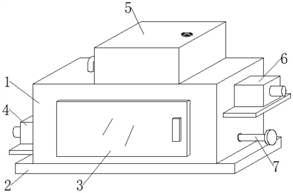
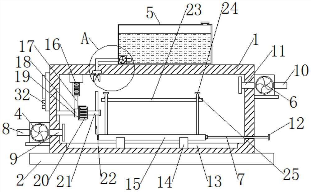
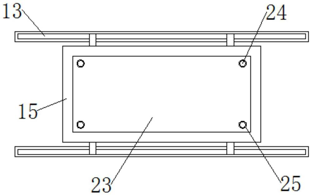
The invention discloses an intelligent metal cutting machine tool for automobile part production, and belongs to the technical field of machine tools. The intelligent metal cutting machine tool for automobile part production comprises a machine tool main body; a safety door is mounted on the outer surface of the machine tool main body; an exhaust fan is mounted below one side of the machine tool main body; and the air inlet end and the air outlet end of the exhaust fan are connected with a first air extraction pipe and a first air exhaust pipe correspondingly. The intelligent metal cutting machine tool for automobile part production is provided with a water tank, a water pump, a water pumping pipe, a water discharging pipe and a grinding head, in the process of cutting a workpiece througha cutter, the water pump operates, water in the water tank can be pumped away through the water pumping pipe, then the water is discharged through the water discharging pipe, and the cutter below is watered, so that the cutter is safer in the cutting process, and spark sputtering is not likely to be caused; and when the cutter is used for a long time and abraded, an air cylinder operates and can pull the cutter to be lifted upwards, so that the cutter makes contact with a grinding head, a motor operates, a rotating shaft drives the cutter to rotate and grind on the grinding head, the sharpnessof the cutter is restored, and the cutter can be continuously used.

Description

technical field [0001] The invention relates to the technical field of numerical control machine tools, in particular to an intelligent metal cutting machine tool used for the production of auto parts. Background technique [0002] A cutting machine tool is a machine tool that mainly uses a turning tool to turn a rotating workpiece. Drills, reamers, reamers, taps, dies and knurling tools can also be used for corresponding processing on the lathe. Lathes are mainly used to process shafts, discs, sleeves and other workpieces with rotating surfaces, and are the most widely used machine tools in machinery manufacturing and repair factories. [0003] According to the Chinese patent with the publication number CN210208883U, a cutting mechanism of a metal cutting machine tool is disclosed. By utilizing the arrangement of the first slide plate and the second slide plate, the first slide block is positioned in the limit groove by sliding the first slide plate. Relatively slide in t...

Claims


Application Information

Patent Timeline
Patent Type & Authority Applications(China)
IPC IPC(8): B23P23/04B23Q11/00B23Q11/10
CPCB23P23/04B23Q11/0046B23Q11/10
Inventor 蒋兰艳
Owner 广州承光电子科技有限公司
Learn More