Yam cleaning, packaging and dicing equipment
A technology of cutting and equipment, applied in the fields of application, food science, food processing, etc., can solve the problems of manual packaging and achieve the effect of easy collection
- Summary
- Abstract
- Description
- Claims
- Application Information
AI Technical Summary
Problems solved by technology
Method used
Image
Examples
Embodiment 1
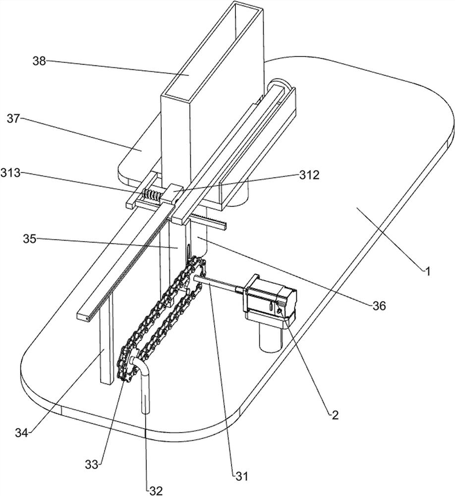
[0025] A kind of equipment for cleaning, packing and cutting yam, such as figure 1 As shown, it includes a base 1, a servo motor 2, a push mechanism 3, a cleaning mechanism 4 and a collection frame 5. A servo motor 2 is provided on the left front side of the top of the base 1, and a push mechanism 3 is provided on the left side of the top of the base 1. The push mechanism 3 The parts are connected with the output shaft of the servo motor 2, and the front side of the top of the base 1 is provided with a cleaning mechanism 4, and the parts of the cleaning mechanism 4 are connected with the output shaft of the servo motor 2, and a collecting frame 5 is placed on the right side of the top of the base 1.
[0026] When people need to clean, pack and cut yams, they first put the yams into the parts of the pushing mechanism 3, connect the parts of the cleaning mechanism 4 with the water tank, and then start the servo motor 2, and the output shaft of the servo motor 2 rotates Drive the...
Embodiment 2
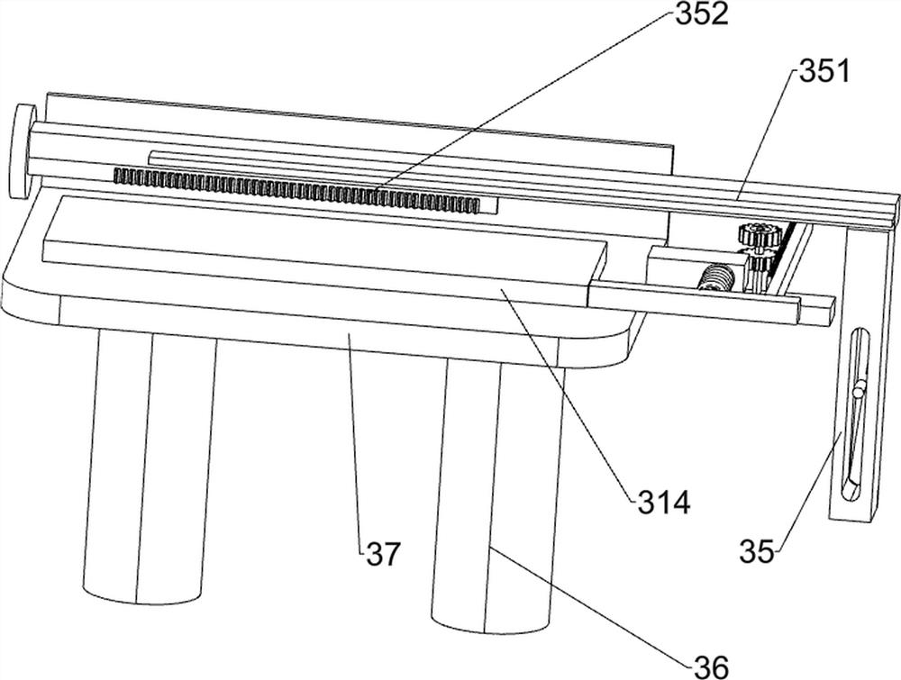
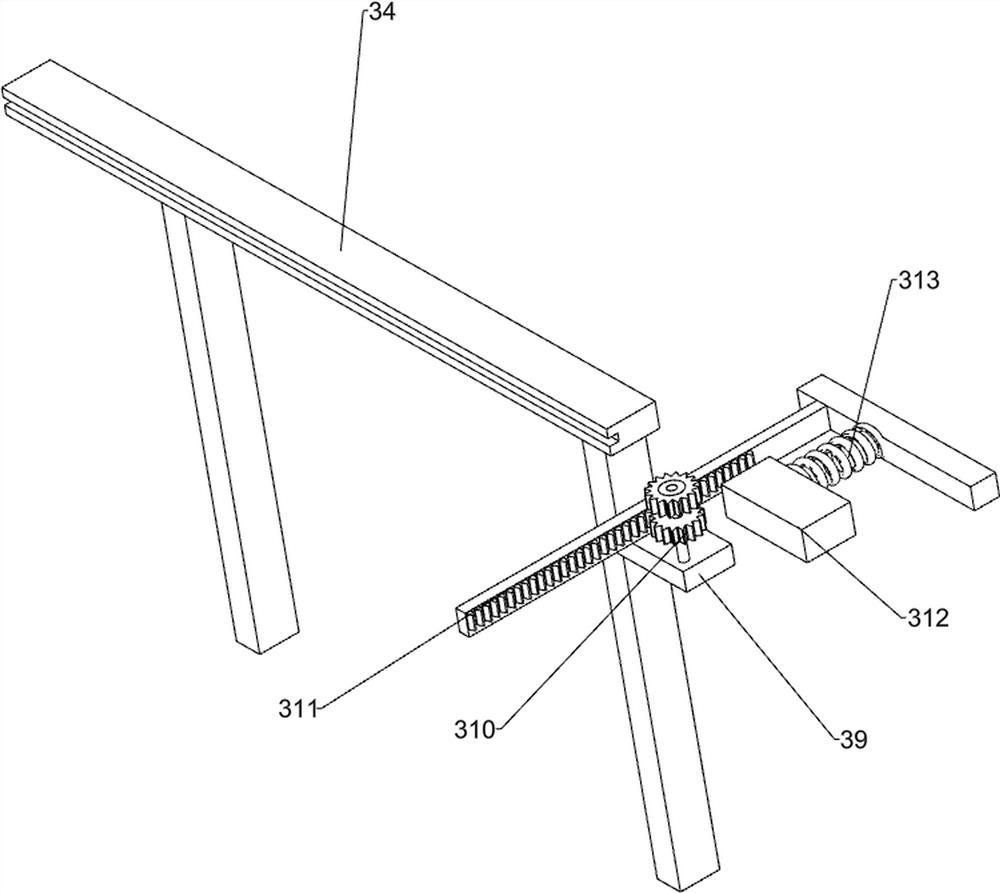
[0028] On the basis of Example 1, such as Figure 2-6As shown, the push mechanism 3 includes a first rotating shaft 31, a fixed rod 32, a sprocket drive assembly 33, a fixed frame 34, a slide rod 35, a push rod 351, a first rack 352, a support column 36, a fixed plate 37, a storage Object box 38, the first fixed block 39, gear set 310, the second rack 311, the second fixed block 312, the first spring 313 and the push block 314, the output shaft of the servo motor 2 is connected with the first rotating shaft 31, the base 1. A fixed rod 32 is provided on the front side of the top of the left side. A sprocket drive assembly 33 is connected between the fixed rod 32 and the first rotating shaft 31. The sprocket drive assembly 33 is connected to the fixed rod 32 in a rotational manner. On the left side of the top of the base 1 is a Fixed mount 34, the front portion of the fixed mount 34 is slidably connected with a slide bar 35, the slide bar 35 is slidably connected with the sprock...
Embodiment 3
[0033] On the basis of Example 2, such as Figure 7 with Figure 8 As shown, a clamping mechanism 6 is also included, and the clamping mechanism 6 includes a drain pipe 61, a push frame 62, a second spring 63, a first wedge rod 64, a blocking block 65, a guide rod 66, a guide frame 67, a second Wedge bar 68 and the 3rd spring 69, connecting frame 418 right parts are provided with drainpipe 61, and drainpipe 61 right side sliding type is connected with push frame 62, and push frame 62 inboard circumferential direction is connected with drainpipe 61 with the second The spring 63, the right part of the push frame 62 is uniformly provided with a first wedge-shaped rod 64 in the circumferential direction, and the right part of the drainage pipe 61 is uniformly provided with a shielding block 65 in the circumferential direction. 65 is connected with guide bar 66, and push frame 62 right part circumferential direction is evenly provided with guide frame 67, and guide frame 67 is pos...
PUM
 Abstract
Description
Claims
Application Information
 - R&D
- Intellectual Property
- Life Sciences
- Materials
- Tech Scout
- Unparalleled Data Quality
- Higher Quality Content
- 60% Fewer Hallucinations
Browse by: Latest US Patents, China's latest patents, Technical Efficacy Thesaurus, Application Domain, Technology Topic, Popular Technical Reports.
© 2025 PatSnap. All rights reserved.Legal|Privacy policy|Modern Slavery Act Transparency Statement|Sitemap|About US| Contact US: help@patsnap.com


