
Automatic cutting device for stone lantern

An automatic cutting device and lantern technology, applied in the direction of used abrasive processing devices, stone processing equipment, stone processing tools, etc., can solve the problems of inability to remove and collect waste, save manpower, expand the scope of use, and reduce waste Effect

Pending Publication Date: 2021-04-09
祝建新
View PDF6 Cites 1 Cited by
  • Summary
  • Abstract
  • Description
  • Claims
  • Application Information

AI Technical Summary

Problems solved by technology

[0005] In order to overcome the shortcomings of manually pushing the lantern and manually adjusting the cutting position in the prior art, and the inability to remove and collect waste materials, the technical problem to be solved is to provide an automatic water pressure cutting that can independently adjust the cutting position, automatically push out waste materials, and facilitate collection. Stone Lantern Automatic Cutting Device for Scrap

Method used


Image

  • Automatic cutting device for stone lantern
  • Automatic cutting device for stone lantern
  • Automatic cutting device for stone lantern

Examples


Embodiment 1

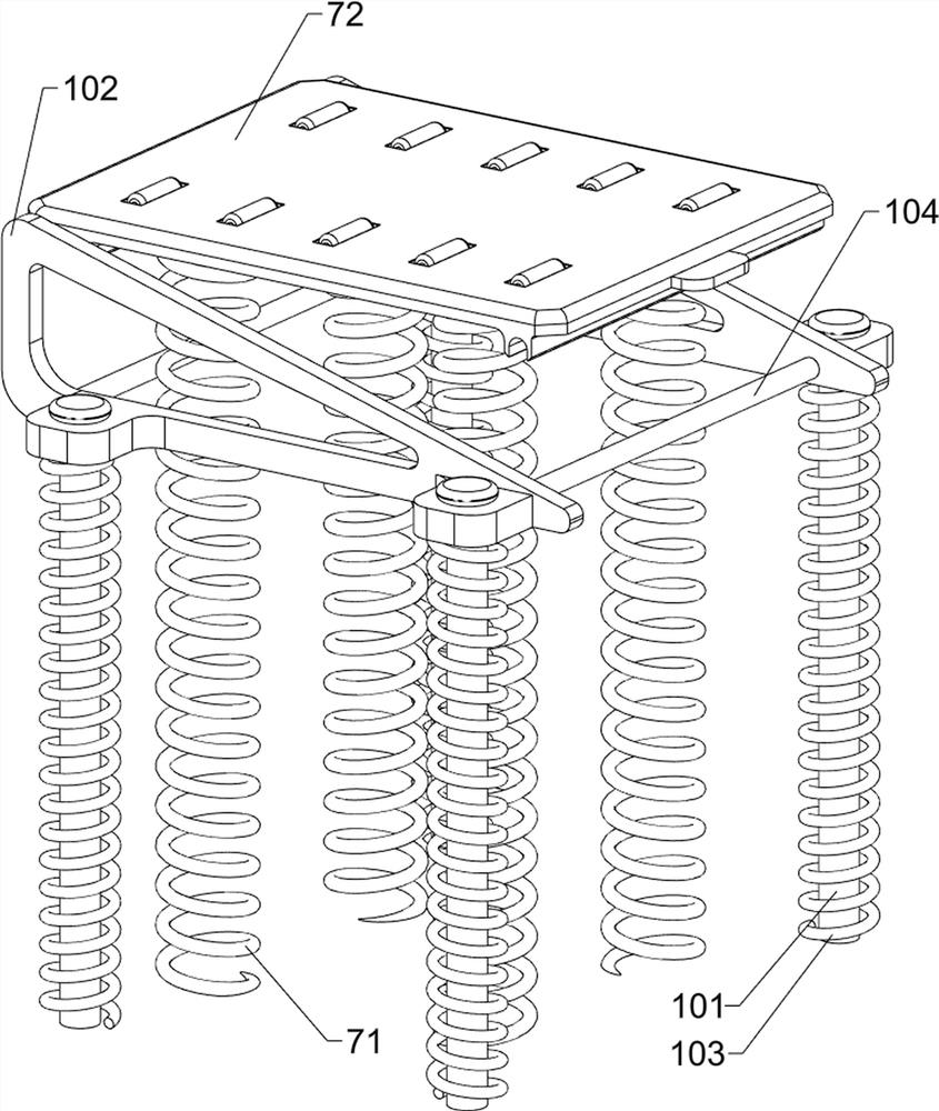
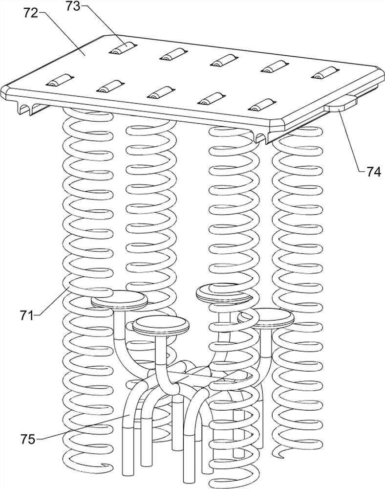
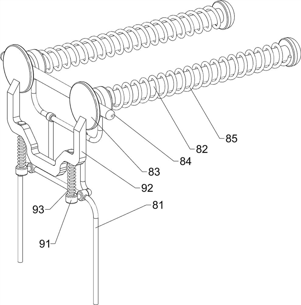
[0031] An automatic cutting device for stone lanterns, such as figure 1 , figure 2 with image 3 As shown, it includes a base 1, a first support frame 2, a motor 3, a placement assembly 4 and a liquid cutting assembly 5, and the first support frame 2 is connected to the front and rear sides of the upper part of the base 1, and the first support frame 2 is connected to the upper part of the base 1. A placement assembly 4 is arranged between them, a liquid cutting assembly 5 is arranged between the upper side of the first support frame 2 , and a motor 3 is installed on the lower part of the liquid cutting assembly 5 .

[0032] The placement assembly 4 includes a support foot 41, a first placement plate 42 and a first roller 43. The right side of the upper part of the base 1 is connected with a support foot 41, and the support foot 41 is connected with the first support frame 2 on both sides. The first support frame 2 A first placement board 42 is connected between the upper s...

Embodiment 2

[0036] On the basis of Example 1, such as Figure 4 , Figure 5 , Image 6 , Figure 7 with Figure 8 As shown, a positioning assembly 6 is also included. The positioning assembly 6 includes a stopper 61, a first wedge-shaped block 62, a slider 63, a first spring 64 and a handle 65. A slider 63 is connected, the upper side of the slider 63 is connected with a first spring 64, the upper side of the first spring 64 is connected with a stopper 61, and the left side of the lower part of the stopper 61 is symmetrically connected with a first wedge-shaped block 62 front and rear, the second A wedge block 62 cooperates with the first placement plate 42 , and a handle 65 is connected to the upper side of the middle part of the stop block 61 .

[0037] When vigorously pushing the lantern to move to the left, it will eventually be blocked by the stopper 61 and cannot move freely. Sometimes it is necessary to adjust the cutting position according to the actual situation. If the posit...


PUM


Abstract

The invention relates to a cutting device, in particular to an automatic cutting device for a stone lantern. According to the automatic cutting device for the stone lantern, water pressure is automatically utilized for cutting, the cutting position can be automatically adjusted, waste materials are automatically pushed out, and the waste materials are conveniently collected. The automatic cutting device for the stone lantern comprises: a base, wherein first supporting frames are connected to the two sides of the upper portion of the base correspondingly; a placing assembly, arranged between the first supporting frames and the upper portion of the base; a liquid cutting assembly, arranged between the upper sides of the first supporting frames; and a motor, mounted at the lower portion of the liquid cutting assembly. By starting a water pump, pressurizing water, spraying the water out of a spray head, starting the motor, driving a middle small belt wheel to rotate and driving a right rear side small belt wheel and a large belt wheel to rotate through a conveying belt, the outer side conveying belt is driven to rotate, the spray head is driven to rotate, and the effect of automatically cutting the stone lantern through water pressure is achieved.

Description

technical field [0001] The invention relates to a cutting device, in particular to an automatic cutting device for stone lanterns. Background technique [0002] Stone lanterns are one of the important contents of Japanese stone culture, and they are also an important variety of Japanese stone products exported from China. Stone lanterns are often used for garden and courtyard decoration. When making stone lanterns, they need to be cut and processed, so that The middle part is hollowed out so that lighting can be placed smoothly. [0003] The existing stone lantern cutting method is to rely on the user to manually push the lantern to the rapid jet of water for cutting, and then remove it. When the cutting position of the stone lantern needs to be adjusted in this method, only Relying on continuous pushing by hand is labor-intensive and dangerous at the same time. The cut stone debris will fall directly and splash everywhere, making it difficult to collect them in one place. ...

Claims


Application Information

Patent Timeline
IPC IPC(8): B24C1/04B24C3/02B24C9/00B28D1/22B28D7/00B28D7/02B28D7/04
CPCB24C1/045B24C3/02B24C9/00B24C9/003B28D1/22B28D7/04B28D7/02B28D7/005B28D7/00
Inventor 祝建新
Owner 祝建新
Learn More