A directional transmission method and device suitable for l valve stem

A technology of directional transmission and valve stem, which is applied in the direction of transportation and packaging, conveyor objects, energy industry, etc., can solve the problems of low pass rate, easy rotation and transposition, small valve stem structure, etc., and achieves convenient and simple operation, The effect of improving production efficiency and improving accuracy

Active Publication Date: 2022-06-07
SOUTHEAST UNIV
View PDF6 Cites 0 Cited by
  • Summary
  • Abstract
  • Description
  • Claims
  • Application Information

AI Technical Summary

Problems solved by technology

like Figure 5 As shown, the L valve stem is small in size and has a special shape. Using a conventional hopper to transport and slightly vibrating, it is impossible to make the L-shaped valve stem accurately enter the trough; and during the transmission process, due to the smooth The lower end of the round tube, the L valve stem with the big head connecting section is very prone to rotation and transposition during the conveying process; at the same time, there must be a gap between the material trough and the L valve stem, so the L valve stem is rolling. It is inevitable to tilt and rotate. When the diagonal line of the L valve stem is close to or smaller than the cross-sectional width of the trough, there is a danger of being stuck or losing orientation.
[0005] However, due to production needs, it is necessary to arrange the L valve stems according to a specific posture and scale when loading materials, so as to complete the subsequent processing of the workpiece; therefore, the existing L valve stems cannot rely on machines for stable transmission, and manual correction is required After that, place it on the conveyor
[0006] It leads to high labor intensity for workers and is not suitable for modern production
At the same time, due to the small structure and irregular shape of the L valve stem, the requirements for workers' operation level are relatively high.
Workers perform repetitive operations, which are tedious and easily distracted, which can easily lead to low product accuracy and low pass rate

Method used


Image

  • A directional transmission method and device suitable for l valve stem
  • A directional transmission method and device suitable for l valve stem
  • A directional transmission method and device suitable for l valve stem

Examples


Embodiment Construction

[0032] In order to deepen the understanding of the present invention, the present invention will be described in further detail below with reference to the accompanying drawings. The embodiments are only used to explain the present invention and do not constitute a limitation on the protection scope of the present invention.

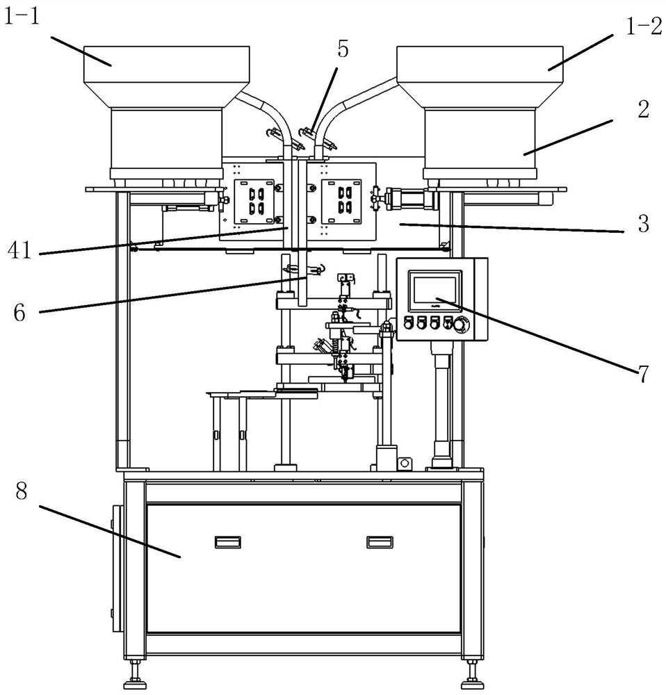
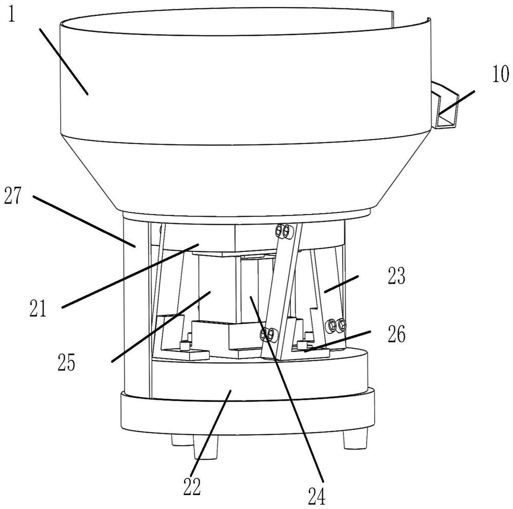
[0033] like Figure 1-4 The directional transmission device of the L valve stem of the present invention is shown. The device adopts a left-right symmetrical design. The inner wall of the hopper 1 is provided with a spirally rising material chute 10;

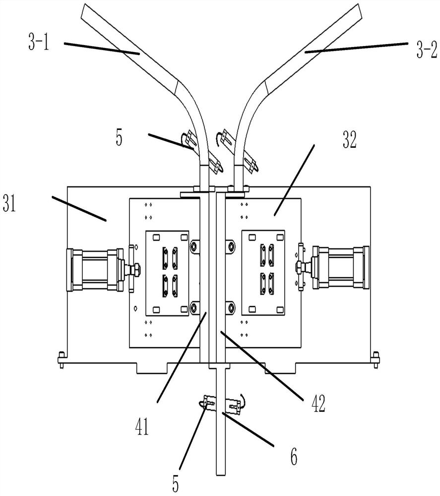
[0034] The hopper 1 includes a left hopper 1-1 and a right hopper 1-2; the valve stem transmission mechanism 3 includes a left channel 3-1 connecting with the left hopper 1-1 and a right channel 3-2 connecting with the right hopper 1-2; the left channel 3 A counting sensor 5 is provided at the exit of -1 and right channel 3-2;

[0035] The left channel 3-1 discharge port is provided with a left moving cha...


PUM


Abstract

The invention relates to the field of automatic processing applicable to L valve stems, in particular to a directional transmission method and device applicable to L valve stems. The directional transmission device applicable to the L valve stem sets the movement mode of the hopper, adding torsional motion to the vibration or up and down movement of the traditional hopper. The spiral trough rises, and the L valve stem and the disc make an upward torsional movement. When the vertical component of the inertial force on the L valve stem is greater than the acceleration of gravity, the L valve stem jumps upward along the spiral groove of the disk; when the vertical component is less than When gravity is accelerated, the L valve stem overcomes the friction force and slides upwards along the spiral groove. This movement makes the L valve stem jump upwards along the spiral groove of the disc and the L valve stem overcomes the friction force and slides upwards along the spiral groove. Feed trough to complete the automatic orientation of the L valve stem.

Description

technical field [0001] The invention belongs to the technical field of industrial automation transmission, and in particular relates to a novel L-valve stem fast and automatic directional transmission technology. Background technique [0002] The normal operation of the production line directly affects the production schedule, production efficiency and production cost. A well-run and adjusted and optimized production line can greatly improve production efficiency and eliminate obstacles between various processing links in the production process of an enterprise. [0003] The workpiece loading and unloading is a key part of the production line, and the speed of loading and unloading directly affects the production efficiency of the entire line. Optimize and adjust the workpiece loading and unloading equipment to further upgrade the production flow, adjust and change in the direction of unmanned and automated, further liberate productivity and improve production efficiency. ...

Claims


Application Information

Patent Timeline
Patent Type & Authority Patents(China)
IPC IPC(8): B65G47/24
CPCB65G47/24Y02P80/10
Inventor 韩良刘健均
Owner SOUTHEAST UNIV
Why Eureka
Try Eureka