Intelligent control method and system based on visual sensors

A visual sensor and intelligent control technology, which is applied in the Internet of Things and smart home applications, can solve problems such as complex threads, and achieve the effects of simplifying the control process, improving use efficiency, and simplifying security management

Active Publication Date: 2021-02-12
WUHAN CITRON INTELLIGENT TECH CO LTD
View PDF11 Cites 5 Cited by
  • Summary
  • Abstract
  • Description
  • Claims
  • Application Information

AI Technical Summary

Problems solved by technology

[0005] According to the technologies disclosed in the above-mentioned prior art, it is not difficult to find that the research direction of the human body visual sensor mainly involves the application combination with the human body sensing scene combined with the multi-sensor, and there are the following technical problems in the above research: the first aspect , the use of smart devices still has a large number of subdivided application scenarios that can be developed, so that the overall expansion of the application ecological chain of smart devices needs to further solve more technical problems. Second, at the same time, with the control of smart application scenarios There are more and more devices involved, and the thread as a whole has become more complex. There is a more complex process from acquisition, information processing, generation of control signals, control signal transmission, and execution of actuators. The more intelligent device information is incorporated into the system Management also means that the control accuracy and control method of the system need to be optimized and improved

Method used


Image

  • Intelligent control method and system based on visual sensors
  • Intelligent control method and system based on visual sensors
  • Intelligent control method and system based on visual sensors

Examples


Embodiment 1

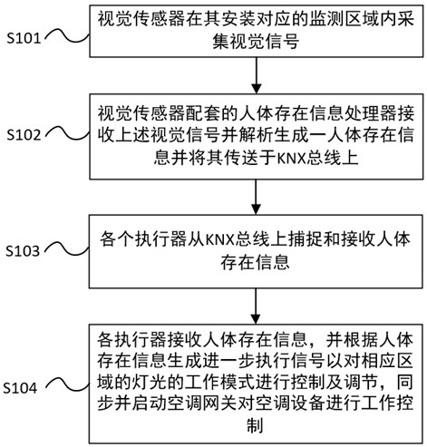
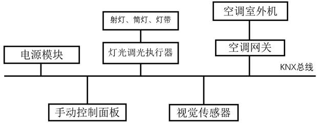
[0073] figure 1 According to the first embodiment of the present invention, it is a flow chart of the intelligent control based on the visual sensor, and assists figure 2 According to the schematic diagram of the smart device connection module under the smart scene application provided by the first embodiment of the present invention, in the composition diagram of the above connection module, the KNX bus integrates a manual control panel, a visual sensor component, an air conditioner gateway, and a lighting controller. Optical actuators, power supply modules for smart devices and other equipment, in which the air-conditioning gateway controls the air-conditioning equipment, and the lighting dimming actuator controls the lighting facilities it manages. According to an office application scenario based on a visual sensor of the present invention The control method in the following embodiment one; Above-mentioned control method specifically comprises the following steps:

[007...

Embodiment 2

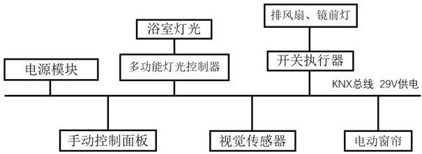
[0104] Figure 5 According to the intelligent system work flow diagram provided by the second embodiment in the present invention, and assist Figure 6 According to the schematic diagram of the intelligent system operating module provided in the second embodiment of the present invention, the solution of the present invention in this embodiment is especially suitable for the application of a toilet use scene in a smart home. In the application of this scene, its specific work The process mainly includes the following steps:

[0105] S201: The visual sensor detects the human body characteristics in the corresponding area of ​​each actuator in the bathroom;

[0106] Specifically, in this embodiment, the visual sensor is installed on the inner wall of the bathroom to collect video information of various locations within the bathroom in real time, and monitor human body characteristics within the bathroom through identification and analysis of the video information.

[0107] S20...

Embodiment 3

[0116] Figure 7 According to the intelligent system work flow chart provided by the third embodiment in the present invention, and assist Figure 8 According to the schematic diagram of the intelligent system operating module provided by the third embodiment of the present invention, the specific workflow of the third embodiment in the exhibition hall environment can be obtained. Of course, the application of the exhibition hall application scene in the third embodiment of the present invention is shared An illustrative embodiment implemented in space according to the inventive concept of the present invention; specifically includes the following steps:

[0117] S301: The visual sensor monitors and identifies the human body features in the exhibition hall area, and identifies customer information based on the human body features to form corresponding customer signals;

[0118] Wherein, in the above S301, the following steps are further included:

[0119] S3011: The visual s...


PUM


Abstract

The invention discloses an intelligent control method and system based on visual sensors, and the visual sensors are arranged in a monitoring space in a partitioning manner, and the method comprises the steps: enabling a plurality of visual sensors to collect visual information based on a current monitoring region, enabling visual processors in one-to-one correspondence with the visual sensors toreceive the visual information, and respectively analyzing and generating a plurality of recognition signals, and transmitting the recognition signals to the intelligent bus; enabling the intelligentsystem to receive the plurality of recognition signals through the intelligent bus and convert the recognition signals into execution signals corresponding to the recognition equipment; and receivingthe execution signal by an actuator corresponding to the intelligent equipment through the intelligent bus, wherein the plurality of recognition signals comprise human body existence signals, and theplurality of recognition signals comprise space coding information of the visual sensor, and are received and recognized by the plurality of actuators in this way, so that omnibearing, full-coverage and high-accuracy real-time monitoring of a monitoring area is realized, and meanwhile, precise and simplified control management of an intelligent system is realized.

Description

technical field [0001] The invention belongs to the field of Internet of Things and smart home applications, and in particular relates to a visual sensor-based control method and system. Background technique [0002] With the advent of the intelligent age, smart home, smart office, etc. and intelligent control have gradually entered all walks of life, and their supporting hardware and software equipment is becoming more and more perfect. Usually, this type of intelligent control system needs to have a central controller (host), controller , actuators, input terminals (including sensors and other input devices), and integrate the facilities and equipment in various intelligent application scenarios such as home / office into the intelligent system to unify the linkage intelligent management. In the application of the above interactive scenarios, the input terminal is used as the system The information input part is a key component of the linkage execution of the intelligent con...

Claims


Application Information

Patent Timeline
Patent Type & Authority Applications(China)
IPC IPC(8): G05B15/02G05B19/418
CPCG05B15/02G05B19/418G05B2219/2642Y02P90/02
Inventor 王世杰
Owner WUHAN CITRON INTELLIGENT TECH CO LTD
Why Eureka
Try Eureka