
Electrical load joint prediction method and device, terminal and storage medium

A forecasting method and electric load technology, applied in forecasting, neural learning methods, instruments, etc., can solve the problem of insufficient data screening and information extraction capabilities of the radial basis function neural network algorithm, low prediction accuracy, and low overall generalization, etc. problem, to achieve the effect of enhancing generalization and robustness, and high prediction accuracy

Pending Publication Date: 2021-02-12
YUNNAN POWER GRID
View PDF3 Cites 3 Cited by
  • Summary
  • Abstract
  • Description
  • Claims
  • Application Information

AI Technical Summary

Problems solved by technology

[0003] Therefore, accurate energy demand forecasting will become an important part of the economic dispatch and optimal operation of the integrated energy system; in traditional energy forecasting problems, usually only the change of a single In the process, the mutual conversion and pivot relationship between different types of loads are obviously ignored.
[0004] Traditional energy forecasting methods include ARMA time series forecasting method, radial basis function neural network method, BP neural network method, etc. The BP neural network algorithm is easily affected by local minimum values ​​in the calculation process, making the overall generalization low; The basic function neural network algorithm is not capable of data screening and information extraction; the time series algorithm is only based on the historical data of a single energy source for load forecasting, and cannot respond to emergencies and abnormal situations in a timely manner, resulting in low forecasting accuracy

Method used


Image

  • Electrical load joint prediction method and device, terminal and storage medium
  • Electrical load joint prediction method and device, terminal and storage medium
  • Electrical load joint prediction method and device, terminal and storage medium

Examples


Embodiment Construction

[0057] The principles and features of the present invention are described below in conjunction with the accompanying drawings, and the examples given are only used to explain the present invention, and are not intended to limit the scope of the present invention.

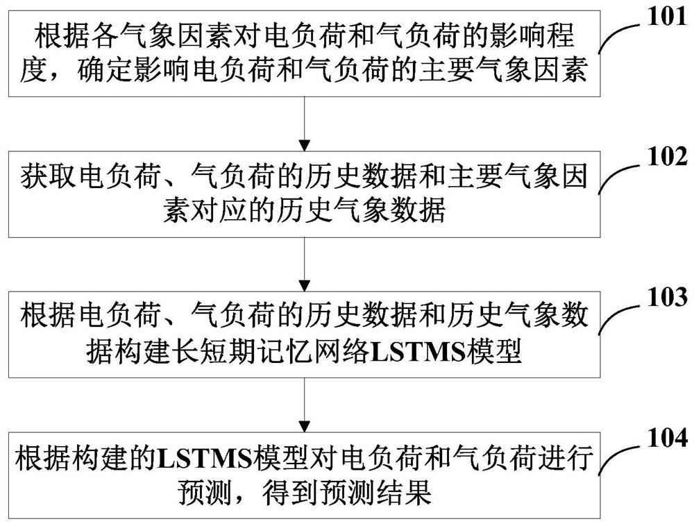
[0058] Such as figure 1 as shown, figure 1 An electrical load joint forecasting method provided in this embodiment, the electrical load joint forecasting method includes:

[0059] S101. Determine the main meteorological factors affecting the electrical load and the gas load according to the degree of influence of each meteorological factor on the electrical load and the gas load;

[0060] S102. Obtain historical data of electrical load and gas load and historical meteorological data corresponding to major meteorological factors;

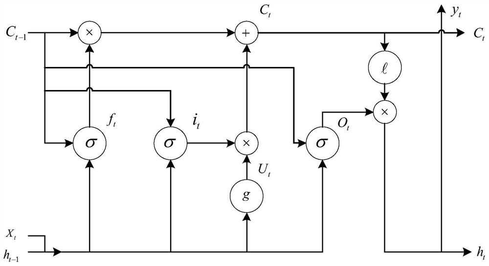
[0061] S103, constructing a long short-term memory network LSTMS model according to the historical data of electric load and gas load and historical meteorological data;

[0062] S104. ...


PUM


Abstract

The invention relates to an electrical load joint prediction method and device, a terminal and a storage medium, and the method comprises the steps: determining main meteorological factors affecting an electrical load and an air load according to the impact degree of each meteorological factor on the electrical load and the air load; acquiring historical data of the electrical load and the gas load and historical meteorological data corresponding to the main meteorological factors; according to the historical data and the historical meteorological data of the electrical load and the gas load,constructing a long-term and short-term memory network LSTMS model; predicting the electrical load and the gas load according to the constructed LSTMS model to obtain a prediction result; consideringthe influence of meteorological factors on the change of the electrical load and the gas load, predicting the electrical load and the gas load by the LSTMS model so that the prediction precision is high, the change trend of the electrical load and the gas load can be well simulated, and a reference can be provided for making a day-ahead operation strategy for a comprehensive energy system.

Description

technical field [0001] The present invention relates to the technical field of energy load forecasting, in particular to a joint electrical load forecasting method, device, terminal and storage medium. Background technique [0002] Under the current background of energy conservation and emission reduction and the rapid growth of renewable energy, building a clean, low-carbon, and environmentally friendly comprehensive energy system has been put on the course of my country's energy development, and has become an important energy source in the process of energy transformation. way of use. The integrated energy system is an integrated energy network in which multiple energy sources interact and mix, and is an important form of development in the energy field. [0003] Therefore, accurate energy demand forecasting will become an important part of the economic dispatch and optimal operation of the integrated energy system; in traditional energy forecasting problems, usually only ...

Claims


Application Information

Patent Timeline
Patent Type & Authority Applications(China)
IPC IPC(8): G06Q10/04G06Q50/06G06F17/18G06N3/04G06N3/08
CPCG06Q10/04G06Q50/06G06N3/049G06N3/08G06F17/18G06N3/045
Inventor 蒋燕何金定李秀峰高道春段睿钦吴洋赵珍玉周彬彬陈凯王有香周涵张聪通栾毅尹成全吴东平
Owner YUNNAN POWER GRID
Learn More