Magnetic core structure for wireless power transmission system

A technology of wireless power transmission and magnetic cores, which is applied in transformer/inductor magnetic cores, electrical components, circuit devices, etc., can solve the problems of low system transmission efficiency and magnetic leakage, so as to improve transmission efficiency, reduce magnetic leakage, reduce The effect of system reluctance

Pending Publication Date: 2021-02-12
SHANGHAI MUNICIPAL ENG DESIGN INST GRP
View PDF0 Cites 0 Cited by
  • Summary
  • Abstract
  • Description
  • Claims
  • Application Information

AI Technical Summary

Problems solved by technology

[0003] The technical problem to be solved by the present invention is to provide a magnetic core structure for a wireless power transmission system in order to overcome the defects of serious magnetic leakage and low system transmission efficiency in the prior art

Method used


Image

  • Magnetic core structure for wireless power transmission system
  • Magnetic core structure for wireless power transmission system
  • Magnetic core structure for wireless power transmission system

Examples


Embodiment 1

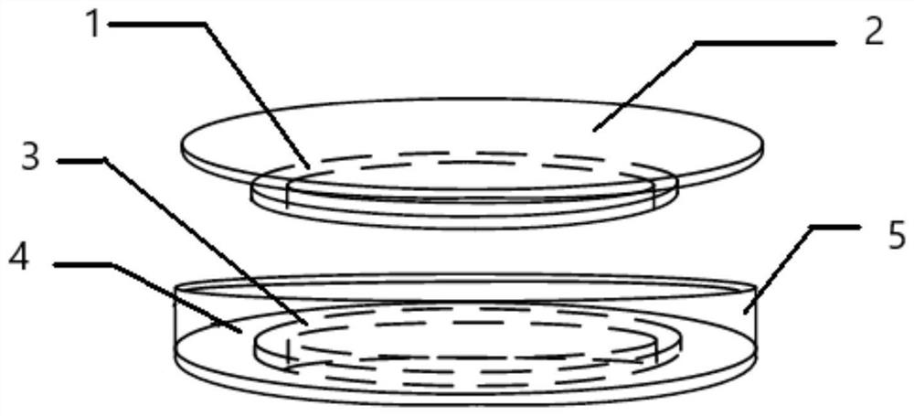
[0035] Such as figure 1 As shown, this embodiment discloses a magnetic core structure for a wireless power transmission system, including: a primary transmitting coil 1, a primary magnetic core 2, a secondary receiving coil 3, and a secondary magnetic core 4;

[0036] The size of the primary side transmitting coil 1 corresponds to the size of the secondary side receiving coil 3; the size of the primary side magnetic core 2 corresponds to the size of the secondary side magnetic core 4;

[0037] The primary side transmitting coil 1 and the secondary side receiving coil 3 are relatively arranged according to a preset distance;

[0038] The primary side magnetic core 2 and the secondary side magnetic core 4 are arranged relative to each other according to a preset distance;

[0039] The primary side magnetic core 2 is provided with at least one through hole, and the through hole is opened in an inner area smaller than the secondary receiving coil 3 .

[0040] In a practicable ma...

Embodiment 2

[0054] Such as figure 1 with Figure 4 As shown, the magnetic core structure used in the wireless power transmission system of this embodiment is a further improvement on Embodiment 1, specifically:

[0055] The magnetic core structure used in the wireless power transmission system of this embodiment also includes a magnetic wall 5;

[0056] The magnetic wall 5 is vertically arranged on the primary magnetic core 2 along the edge of the primary magnetic core 2 .

[0057] In a preferred embodiment, the magnetic wall 5 is a hollow cylinder.

[0058] In one embodiment, the thickness of the magnetic wall 5 ranges from 6 mm to 10 mm.

[0059] Preferably, the thickness of the magnetic wall 5 is 8 mm, but it is not limited thereto, and can be adjusted accordingly according to actual needs.

[0060] In one embodiment, the height of the magnetic wall 5 ranges from 25 mm to 35 mm.

[0061]Preferably, the height of the magnetic wall 5 is 30 mm, but it is not limited thereto, and can ...


PUM

PropertyMeasurementUnit
Diameteraaaaaaaaaa
Thicknessaaaaaaaaaa
Heightaaaaaaaaaa

Abstract

The invention discloses a magnetic core structure for a wireless power transmission system. The magnetic core structure comprises a primary side transmitting coil, a primary side magnetic core, a secondary side receiving coil and a secondary side magnetic core, the size of the primary side transmitting coil corresponds to the size of the secondary side receiving coil; the size of the primary sidemagnetic core corresponds to the size of the secondary side magnetic core; the primary side transmitting coil and the secondary side receiving coil are oppositely arranged according to a preset distance; the primary side magnetic core and the secondary side magnetic core are oppositely arranged according to a preset distance; the primary side magnetic core is provided with at least one through hole, and the through hole is formed in an inner side area smaller than the secondary side receiving coil. The magnetic core structure for the wireless electric energy transmission system can effectivelyreduce the magnetic resistance of the system, improve the transmission efficiency inside the system, effectively reduce the external magnetic leakage of the system, and reduce the electromagnetic radiation of the system to the external space.

Description

technical field [0001] The invention relates to a magnetic core, in particular to a magnetic core structure used in a wireless power transmission system. Background technique [0002] The magnetic core has the characteristics of high magnetic permeability and low magnetic loss, and can improve the transmission efficiency of loosely coupled transformers, so it is widely used in robot wireless charging systems. The magnetic core structures used in the robot wireless charging system are circular groove type, square type, etc. Due to the large gap between the coils of the existing round slot magnetic core, the magnetic leakage of the system is serious; the magnetic resistance of the air is much larger than that of the magnetic core, which makes the magnetic resistance of the system larger, resulting in low system efficiency. Contents of the invention [0003] The technical problem to be solved by the present invention is to provide a magnetic core structure for a wireless pow...

Claims


Application Information

Patent Timeline
IPC IPC(8): H02J50/10H01F27/24
CPCH01F27/24H02J50/10H02J50/005
Inventor 吴晓春
Owner SHANGHAI MUNICIPAL ENG DESIGN INST GRP
Why Eureka
Try Eureka