Combined microphone mesh enclosure and production process
A microphone and combined technology, which is applied in the field of combined microphone grille and production technology, can solve the problems of easy corrosion, high cost, complicated process, etc., and achieve the effect of meeting application requirements, simple structure and easy manufacture
- Summary
- Abstract
- Description
- Claims
- Application Information
AI Technical Summary
Problems solved by technology
Method used
Image
Examples
Embodiment 1
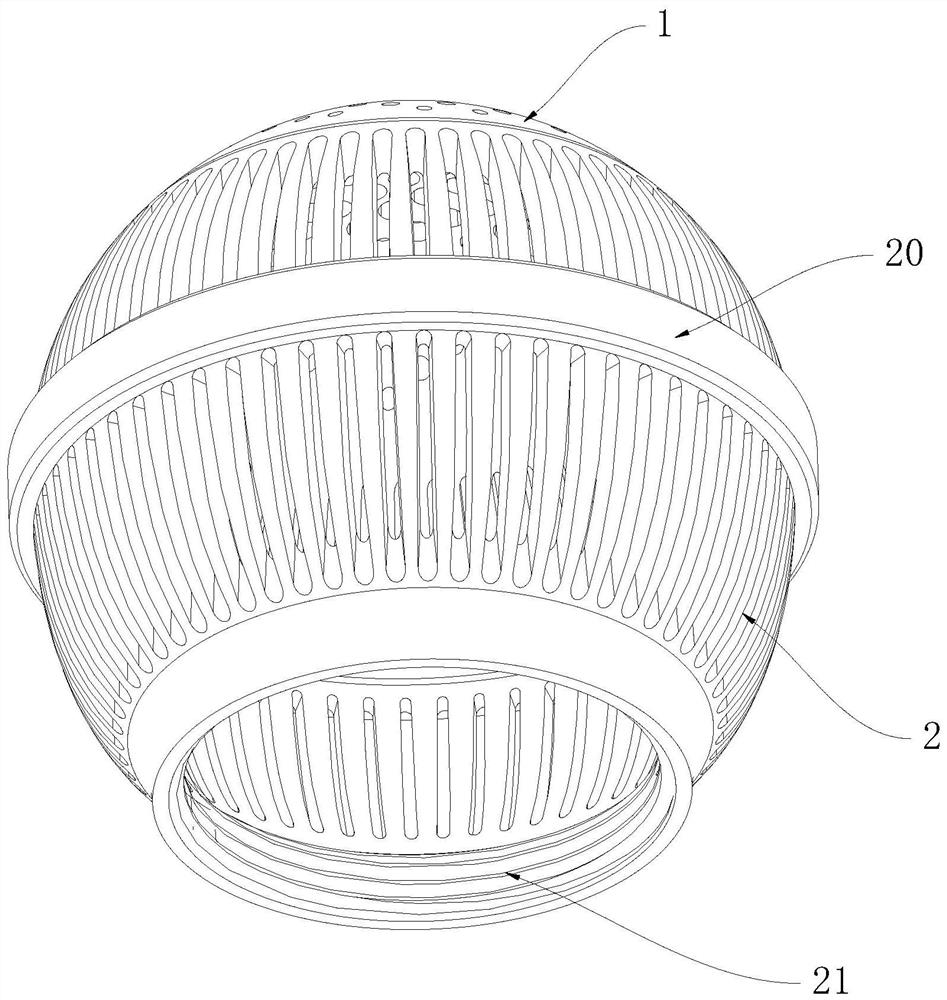
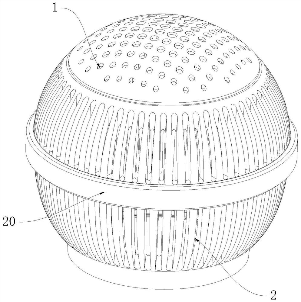
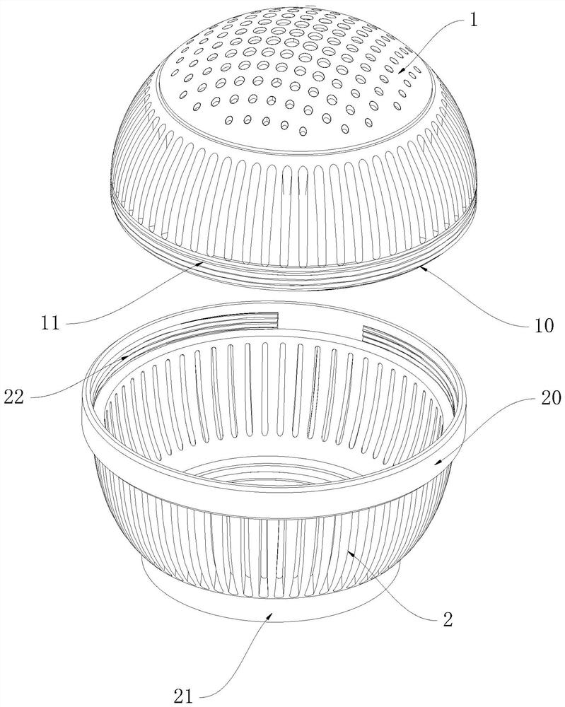
[0026] This embodiment proposes a combined microphone grille, which combines Figure 1 to Figure 3 As shown, it includes a hemispherical upper cover body 1 and a cylindrical lower cover body 2, the side walls of the upper cover body 1 and the side walls of the lower cover body 2 are hollow-shaped, the said A lower connection ring 20 is formed at the upper end opening of the lower cover body 2, and a threaded sleeve 21 for matching with the microphone body is formed at the lower end opening of the lower cover body 2. The inner diameter of the threaded sleeve 21 is smaller than that of the lower connection The inner diameter of the ring 20, an upper connecting ring 10 is formed at the lower end opening of the upper cover 1, and the upper connecting ring 10 and the lower connecting ring 20 are detachably matched.
[0027] In the above structure, the upper cover body 1 and the lower cover body 2 are set as two independent components, and at the same time, a lower connecting ring 2...
Embodiment 2
[0032] As a preferred embodiment of the present invention, in this embodiment, please refer to Figure 4 , the upper connecting ring 10 and the lower connecting ring 20 are engaged with each other.
[0033] In order to realize the snap-fit connection, in this embodiment, a plurality of “L”-shaped sliding grooves 12 are formed on the outer side wall of the upper connecting ring 10 , and one end of the sliding grooves 12 extends longitudinally to the upper connecting ring 10 At the edge of the upper connecting ring 10, the other end of the sliding groove 12 extends for a predetermined length along the circumferential direction of the upper connecting ring 10, and a plurality of sliding blocks 23 are formed on the outer side wall of the lower connecting ring 20. The sliding blocks 23 and The sliding grooves 12 are in one-to-one correspondence, and when the upper connecting ring 10 is inserted into the lower connecting ring 20 and rotates by a predetermined angle, the slider 23 ...
Embodiment 3
[0037] As a preferred embodiment of the present invention, in this embodiment, please refer to Figure 5 , the upper connecting ring 10 and the lower connecting ring 20 are engaged with each other.
[0038] In order to realize the snap connection, in this embodiment, a plurality of slots 13 are formed on the side wall of the upper connecting ring 10, and a plurality of snaps 24 are formed on the outer side wall of the lower connecting ring 20. The snaps 24 One-to-one correspondence with the slot holes 13 , and the buckles 24 are clamped in the slot holes 13 .
[0039] In order to facilitate the snap 24 to be snapped into the slot hole 13 , in this embodiment, a wedge-shaped surface 240 is formed on the top of the snap 24 .
[0040] Based on the above-mentioned embodiment, the present invention also relates to a production process of a combined microphone mesh cover, wherein the microphone mesh cover includes a hemispherical upper cover body and a cylindrical lower cover body....
PUM
 Abstract
Description
Claims
Application Information
 - R&D
- Intellectual Property
- Life Sciences
- Materials
- Tech Scout
- Unparalleled Data Quality
- Higher Quality Content
- 60% Fewer Hallucinations
Browse by: Latest US Patents, China's latest patents, Technical Efficacy Thesaurus, Application Domain, Technology Topic, Popular Technical Reports.
© 2025 PatSnap. All rights reserved.Legal|Privacy policy|Modern Slavery Act Transparency Statement|Sitemap|About US| Contact US: help@patsnap.com


