Sludge treatment device for sewage sedimentation tank

A sludge treatment and sedimentation tank technology, which is applied to the feeding/discharging devices of sedimentation tanks, sedimentation separation, chemical instruments and methods, etc. Effect

Inactive Publication Date: 2021-02-19
伏勇军
View PDF1 Cites 0 Cited by
  • Summary
  • Abstract
  • Description
  • Claims
  • Application Information

AI Technical Summary

Problems solved by technology

[0003] The currently published Chinese patent authorization announcement number is CN108499168A, an environmentally friendly sludge cleaning device for sewage sedimentation tanks. Although the sludge can be extracted and processed, the equipment cannot adjust the orientation of the sludge extraction device during work, thus affecting the use of the equipment.

Method used


Image

  • Sludge treatment device for sewage sedimentation tank
  • Sludge treatment device for sewage sedimentation tank
  • Sludge treatment device for sewage sedimentation tank

Examples


Embodiment 1

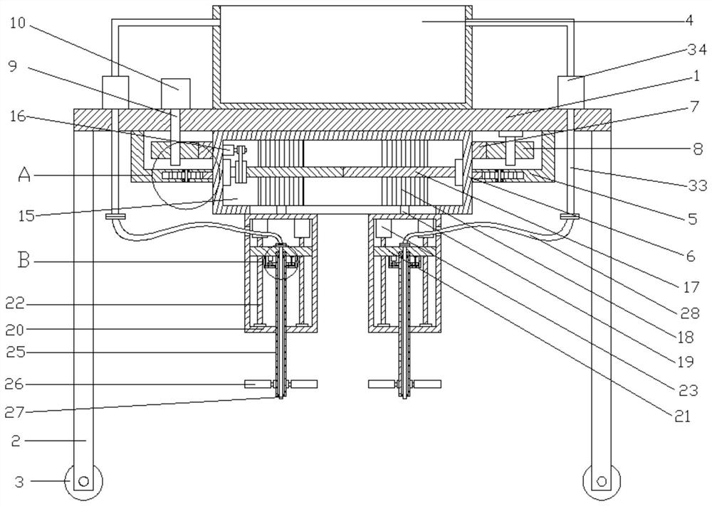
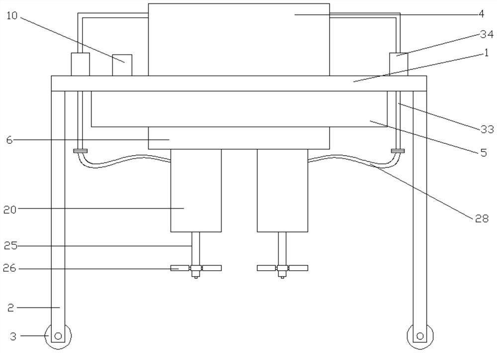
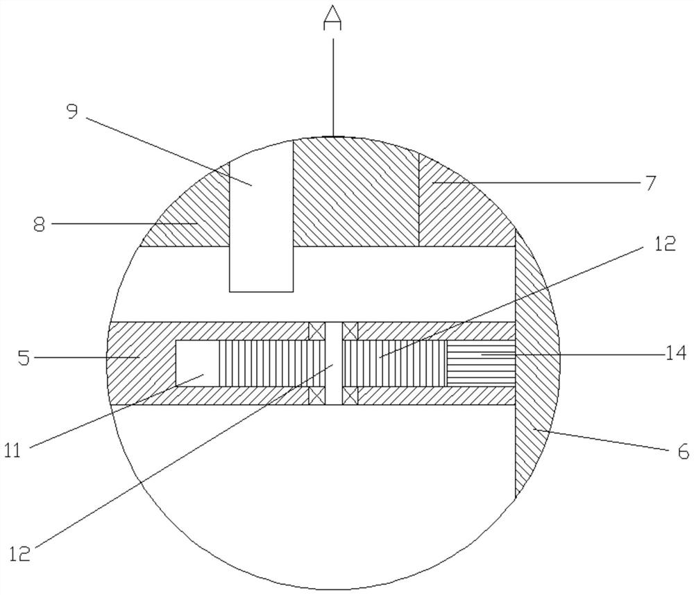
[0027] refer to Figure 1~5 , in an embodiment of the present invention, a sludge treatment device for a sewage settling tank includes a top plate 1, a support column 2 is fixedly installed at the four corners of the lower side of the top plate 1, and a roller 3 is provided at the lower end of the support column 2, which can facilitate the movement of the equipment. A silt storage tank 4 is installed in the middle of the upper side of the top plate 1 for storing the extracted silt. A first connection cover 5 is fixedly installed on the lower side of the top plate 1, and a swivel seat 6 is arranged in the middle of the first connection cover 5, which is located in the second A first external gear 7 is fixedly installed on the outer side of the rotary seat 6 inside the connecting cover 5, and the first external gear 7 is provided with a first connecting gear 8 on the left and right sides, and the first rotating shaft 9 is installed inside the first connecting gear 8, and the left...

Embodiment 2

[0033] The difference from Embodiment 1 is that the connection pool between the rotating seat 6 and the first connection cover 5 is provided with a connection groove 11, and the left and right ends of the connection groove 11 are connected with the second connection gear 13 through the second rotating shaft 12, and the second A second external gear 14 is threadedly connected between the connecting gears 13, and the second external gear 14 is installed on the outside of the rotating base 6. During the rotation of the rotating base 6, the second external gear 24 drives the second connecting gear 13 to rotate. , so that the second connecting gear 13 can limit the rotation base 6, so as to facilitate the stable rotation of the rotation base 6.


PUM


Abstract

The invention relates to the field of environmental protection, in particular to a sludge treatment device for a sewage sedimentation tank. The sludge treatment device comprises a top plate, support columns are mounted on the lower side of the top plate, rollers are arranged at the lower ends of the support columns, a first connecting cover is mounted on the lower side of the top plate, a rotatingbase is arranged in the middle of the first connecting cover, a sliding groove is formed in the rotating base, and a bidirectional threaded rod is mounted in the sliding groove, sliding blocks are connected to the two ends of the bidirectional threaded rod, connecting cavities are formed in the lower sides of the sliding blocks through connecting blocks, moving plates are arranged in the connecting cavities, one-way threaded rods are installed at the four corners of each moving plate, stirring blades are installed on a rotating pipe, second connecting covers are installed on the outer sides of the joints of the rotating pipe and the moving plates, and third outer gears are installed on the rotating pipe. Third connecting gears are engaged with the two sides of the third outer gear, a first silt pumping pipe is installed in the rotating pipe, and a second liquid pumping pipe is installed on the upper side of the first silt pumping pipe through a connecting hose. The direction of the sky boundary sludge pumping device can be effectively facilitated so that the equipment is convenient to use.

Description

technical field [0001] The invention relates to the field of environmental protection, in particular to a sludge treatment device for a sewage sedimentation tank. Background technique [0002] Sewage treatment is the process of purifying sewage to meet the water quality requirements for discharge into a certain water body or reuse. Sewage treatment is widely used in various fields such as construction, agriculture, transportation, energy, petrochemical, environmental protection, urban landscape, medical treatment, catering, etc., and more and more enters the daily life of ordinary people. In the process of sewage treatment, often The sedimentation tank is used to settle the impurities in the sewage, which requires the use of a sludge treatment device to collect and treat the sludge. [0003] The currently published Chinese patent authorization announcement number is CN108499168A, an environmentally friendly sludge cleaning device for sewage sedimentation tanks. Although the...

Claims


Application Information

Patent Timeline
IPC IPC(8): B01D21/24
CPCB01D21/245
Inventor 伏勇军
Owner 伏勇军
Why Eureka
Try Eureka