A silicon-manganese alloy crushing equipment for metallurgical smelting
A technology of silicomanganese alloy and shards, which is applied in the field of silicomanganese alloy shards equipment for metallurgical smelting, can solve the problems of manpower consumption, low processing efficiency, and potential safety hazards, and achieve the effect of reducing labor intensity and potential safety hazards
- Summary
- Abstract
- Description
- Claims
- Application Information
AI Technical Summary
Problems solved by technology
Method used
Image
Examples
Embodiment 1
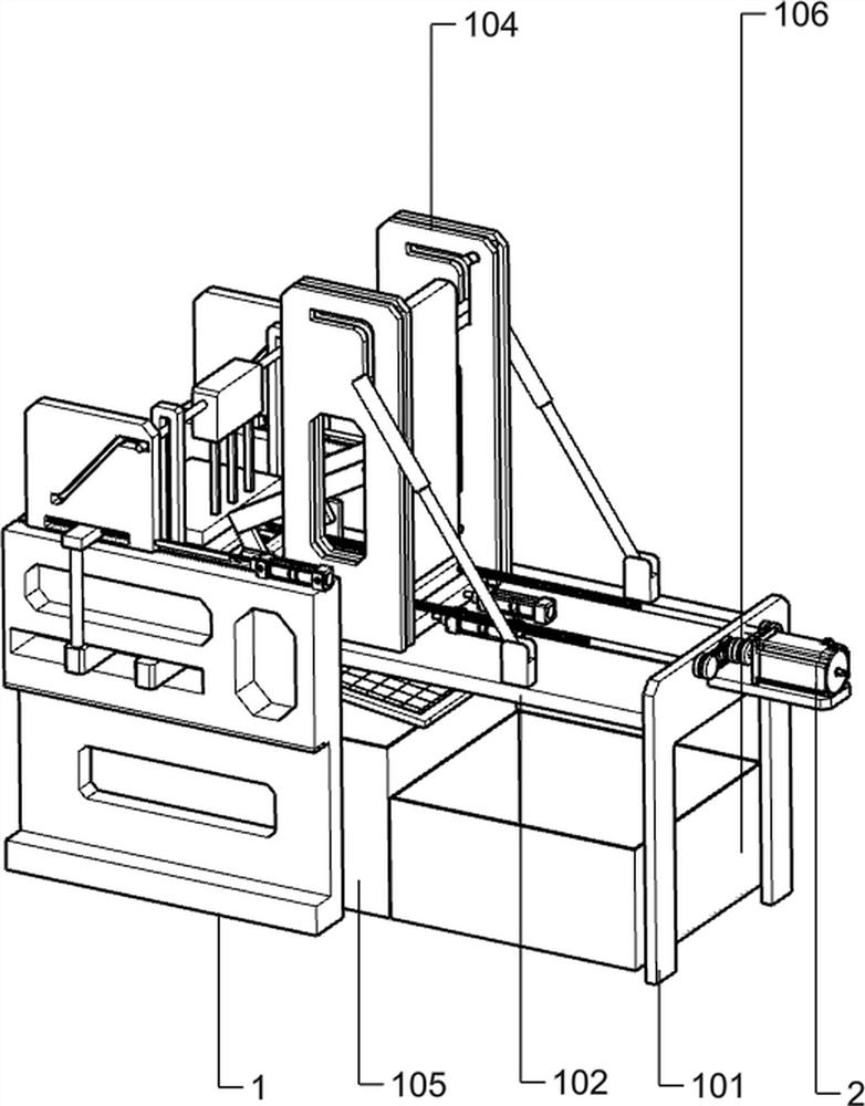
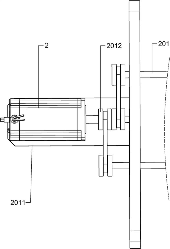
[0027] A kind of silicon-manganese alloy crushing equipment for metallurgical smelting, such as figure 1 As shown, it includes a side support plate 1, a leg 101, a horizontal plate 102, a motor 2, a screw 201, a frame 2011, a pulley 2012, a feeding assembly, a gland assembly, a toggle assembly, a knock assembly 1 and a knock assembly. As for component 2, there are two side support plates 1 symmetrically arranged front and back, and the horizontal plate 102 is fixedly connected to the inside of the two side support plates 1, and there are two supporting legs 101, and the supporting legs 101 are symmetrically arranged left and right along the horizontal plate 102, and the horizontal plate 102 is arranged symmetrically. Both sides of the plate 102 are fixedly connected to the two supporting legs 101, the left side of the frame 2011 is fixedly connected to the upper right side of the right end of the supporting leg 101, the motor 2 is fixedly connected to the upper side of the fram...
Embodiment 2
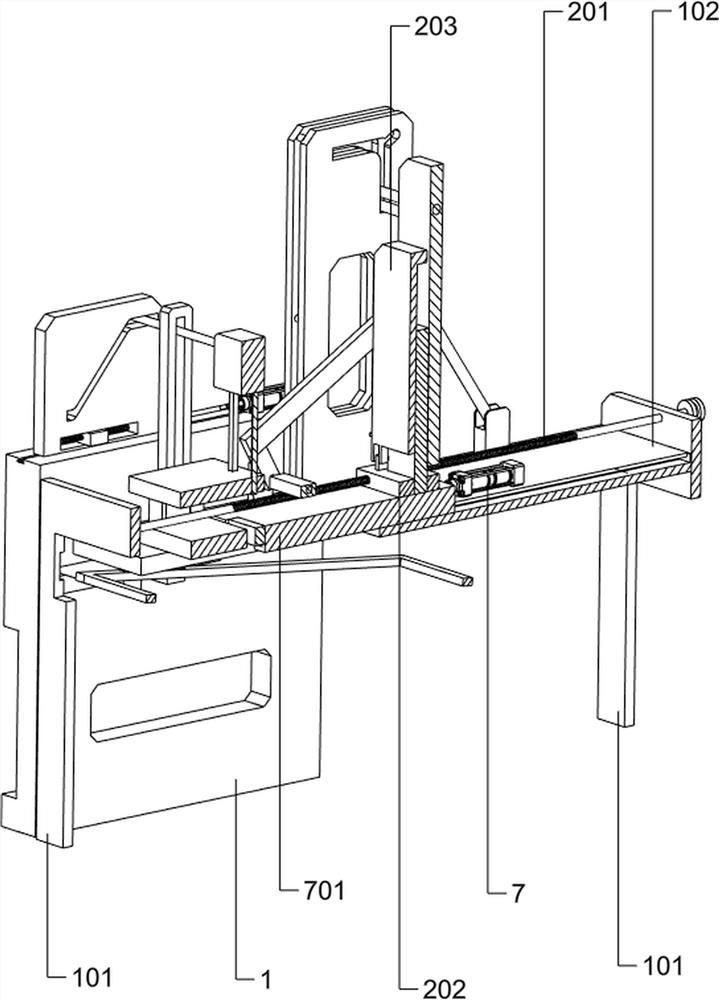
[0030] On the basis of Example 1, such as Figure 2-6 As shown, the feeding assembly includes a nut plate 202, a material plate 203, a small vertical plate 204, a molded rod, a rotating shaft 206 and a connecting plate one 207, and there are two threaded holes on the nut plate 202, which are connected to the two screw rods 201 The thread fits, the material plate 203 is rotatably connected to the nut plate 202, the small vertical plate 204 is symmetrically arranged on the front and rear sides of the horizontal plate 102, and there are two rotating shafts 206, and the rotating shaft 206 is rotatably connected to the small vertical plate 204. 207 is fixedly connected on two rotating shafts 206, two L-shaped rods 205 are symmetrically arranged, the left lower end of the L-shaped rod 205 is fixedly connected with the rotating shaft 206, and the right upper end of the L-shaped rod 205 is rotationally connected with the material plate 203.
[0031] When loading materials, the staff f...
Embodiment 3
[0043] On the basis of Example 2, such as Figure 6-7 As shown, it also includes connecting rod 6, cylinder 601, long spring 6011, connecting plate three 602, screen 603, barrel one 105 and barrel two 106, long spring 6011, connecting rod 6 and cylinder 601 along the horizontal plate 102 Symmetrically arranged, the left and right ends of the long spring 6011 are fixedly connected in the groove of the sliding plate 501 close to the side support plate 1, the connecting rod 6 is fixedly connected to the middle of the long spring 6011, the cylinder 601 is fixedly connected to the lower end of the connecting rod 6, and the cylinder 601 The lower end of the cylinder is fixedly connected with the connecting plate three 602, the connecting plate three 602 is connected with the screen 603, and the barrel one 105 and the barrel two 106 are placed side by side at the bottom of the screen 603.
[0044] The broken silico-manganese plates will fall onto the screen 603 along the groove on th...
PUM
 Abstract
Description
Claims
Application Information
 - R&D
- Intellectual Property
- Life Sciences
- Materials
- Tech Scout
- Unparalleled Data Quality
- Higher Quality Content
- 60% Fewer Hallucinations
Browse by: Latest US Patents, China's latest patents, Technical Efficacy Thesaurus, Application Domain, Technology Topic, Popular Technical Reports.
© 2025 PatSnap. All rights reserved.Legal|Privacy policy|Modern Slavery Act Transparency Statement|Sitemap|About US| Contact US: help@patsnap.com


