
Silicon-manganese alloy crushing equipment for metallurgical smelting

A technology of silicomanganese alloy and shards, which is applied in the field of silicomanganese alloy shards equipment for metallurgical smelting, can solve the problems of manpower consumption, safety hazards, and low processing efficiency, and achieve the effect of reducing labor intensity and safety hazards

Active Publication Date: 2021-02-19
新疆西部合盛硅材料有限公司
View PDF8 Cites 2 Cited by
  • Summary
  • Abstract
  • Description
  • Claims
  • Application Information

AI Technical Summary

Problems solved by technology

[0004] In order to overcome the shortcomings of manually crushing silicon-manganese alloys, which are very labor-intensive, low in processing efficiency, and have certain safety hazards, the technical problem to be solved is: to provide a metallurgical smelting process that can reduce the labor intensity of the work, has high processing efficiency, and is safe and simple. Silicon-manganese alloy crushing equipment

Method used


Image

  • Silicon-manganese alloy crushing equipment for metallurgical smelting
  • Silicon-manganese alloy crushing equipment for metallurgical smelting
  • Silicon-manganese alloy crushing equipment for metallurgical smelting

Examples


Embodiment 1

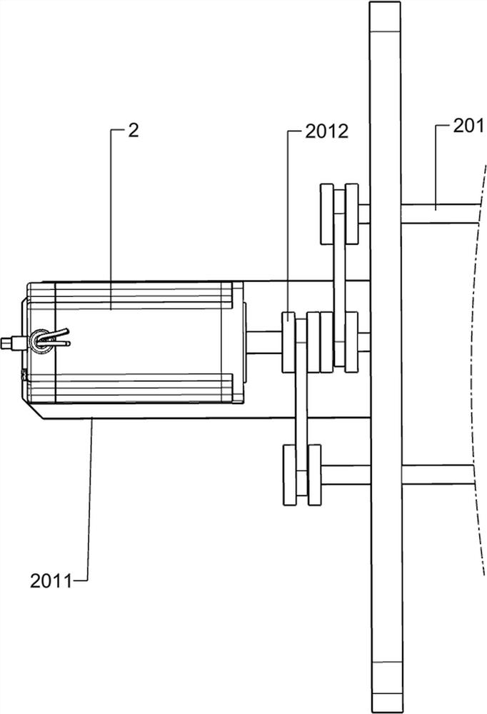
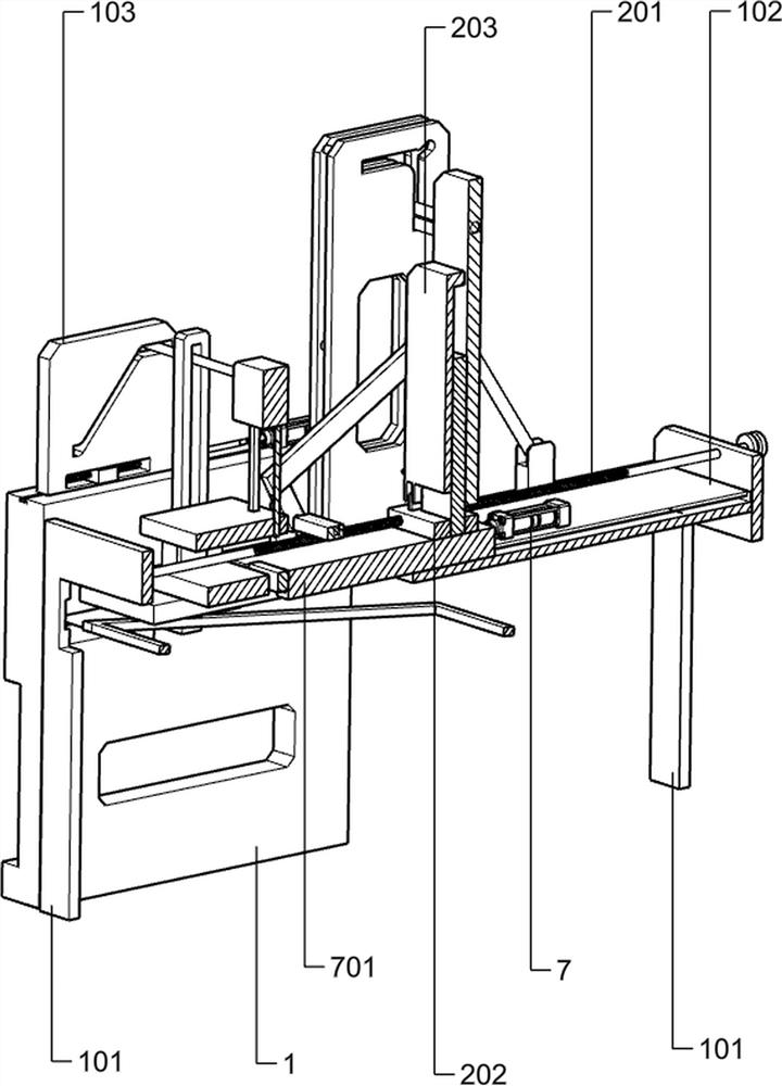
[0027] A kind of silicon-manganese alloy crushing equipment for metallurgical smelting, such as figure 1 As shown, it includes a side support plate 1, a leg 101, a horizontal plate 102, a motor 2, a screw 201, a frame 2011, a pulley 2012, a feeding assembly, a gland assembly, a toggle assembly, a knock assembly 1 and a knock assembly. As for component 2, there are two side support plates 1 front and back symmetrically arranged, and the horizontal plate 102 is fixedly connected to the inner side of the two side support plates 1, and there are two supporting legs 101, and the supporting legs 101 are symmetrically arranged left and right along the horizontal plate 102, Both sides of the horizontal plate 102 are fixedly connected to the two supporting legs 101, the left side of the frame 2011 is fixedly connected to the upper right side of the right end of the supporting leg 101, the motor 2 is fixedly connected to the upper side of the frame 2011, and the screw rod 201 runs along ...

Embodiment 2

[0030] On the basis of Example 1, such as Figure 2-6 As shown, the feeding assembly includes a nut plate 202, a material plate 203, a small vertical plate 204, a molded rod, a rotating shaft 206 and a connecting plate one 207, and there are two threaded holes on the nut plate 202, which are connected to the two screw rods 201 The thread fits, the material plate 203 is rotatably connected to the nut plate 202, the small vertical plate 204 is symmetrically arranged on the front and rear sides of the horizontal plate 102, and there are two rotating shafts 206, and the rotating shaft 206 is rotatably connected to the small vertical plate 204. 207 is fixedly connected on two rotating shafts 206, two L-shaped rods 205 are symmetrically arranged, the left lower end of the L-shaped rod 205 is fixedly connected with the rotating shaft 206, and the right upper end of the L-shaped rod 205 is rotationally connected with the material plate 203.

[0031] When loading materials, the staff f...

Embodiment 3

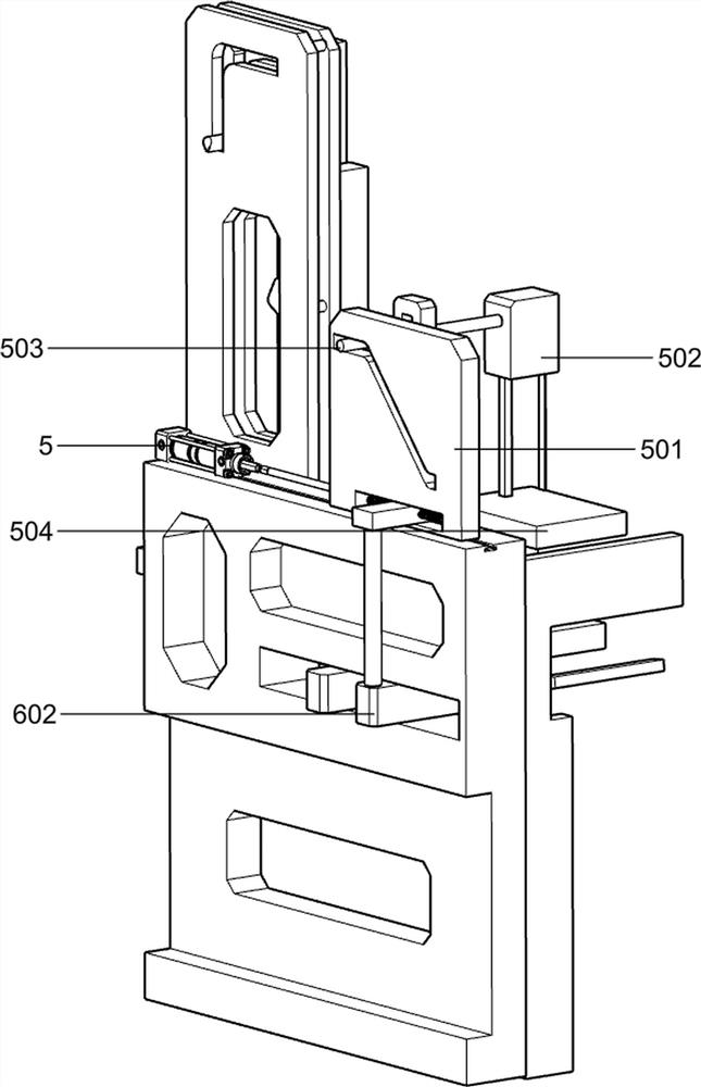
[0043] On the basis of Example 2, such as Figure 6-7 As shown, it also includes connecting rod 6, cylinder 601, long spring 6011, connecting plate three 602, screen 603, barrel one 105 and barrel two 106, long spring 6011, connecting rod 6 and cylinder 601 along the horizontal plate 102 Symmetrically arranged, the left and right ends of the long spring 6011 are fixedly connected in the groove of the sliding plate 501 close to the side support plate 1, the connecting rod 6 is fixedly connected to the middle of the long spring 6011, the cylinder 601 is fixedly connected to the lower end of the connecting rod 6, and the cylinder 601 The lower end of the cylinder is fixedly connected with the connecting plate three 602, the connecting plate three 602 is connected with the screen 603, and the barrel one 105 and the barrel two 106 are placed side by side at the bottom of the screen 603.

[0044] The broken silico-manganese plates will fall onto the screen 603 along the groove on th...


PUM


Abstract

The invention relates to crushing equipment, in particular to silicon-manganese alloy crushing equipment for metallurgical smelting. The technical problem is to provide the silico-manganese alloy crushing equipment for the metallurgical smelting that can reduce the labor intensity of works, has high processing efficiency, and is safe and simple. According to the technical scheme, the silicon-manganese alloy crushing equipment for the metallurgical smelting comprises side supporting plates, supporting legs, a transverse plate and the like; the two side supporting plates are symmetrically arranged; the transverse plate is fixedly connected to the inner sides of the two side supporting plates; and the two supporting legs are symmetrically arranged along one center line of the transverse plate, and the other two sides of the transverse plate are fixedly connected to the two supporting legs. According to the silico-manganese alloy crushing equipment for the metallurgical smelting provided by the invention, a knocking assembly I can crush vertical silicon-manganese alloy plates successively, small chippings can directly fall off from a linear through groove on the transverse plate, largechippings can be pushed to the bottom of a knocking assembly II and crushed again through the knocking assembly II, and therefore the purpose of replacing manpower to crush silicon-manganese alloy isachieved.

Description

technical field [0001] The invention relates to a crushing device, in particular to a silicon-manganese alloy crushing device for metallurgical smelting. Background technique [0002] Manganese-silicon alloy is a compound deoxidizer commonly used in steelmaking. It is an alloy composed of manganese, silicon, iron, a small amount of carbon and other elements. Its application demand in the market has been rising. For its processing and crushing, it is generally done manually It is very labor-intensive to knock and break the silicon-manganese alloy manually with a hammer, and the processing efficiency is also very low, and it has certain safety hazards. [0003] Therefore, it is necessary to develop a silicon-manganese alloy fragment equipment for metallurgical smelting that can reduce the labor intensity of work, has high processing efficiency, and is safe and simple. Contents of the invention [0004] In order to overcome the shortcomings of manually crushing silicon-manga...

Claims


Application Information

Patent Timeline
IPC IPC(8): B02C1/14B02C23/02B02C23/14B02C23/16
CPCB02C1/14B02C1/005B02C23/02B02C23/14B02C23/16B02C2023/165
Inventor 杨天
Owner 新疆西部合盛硅材料有限公司
Learn More