Injector crushing device for medical waste recovery

A technology for crushing device and medical waste, which can be used in instruments, alarms, grain processing, etc.

Active Publication Date: 2021-02-19
汕尾市广业环保科技有限公司
View PDF14 Cites 8 Cited by
  • Summary
  • Abstract
  • Description
  • Claims
  • Application Information

AI Technical Summary

Problems solved by technology

[0004] In order to overcome the shortcomings of the traditional grinder that needs to be manually put into the syringe continuously, and the workload is relatively large, such as putting it in at one time, which affects the quality of

Method used


Image

  • Injector crushing device for medical waste recovery
  • Injector crushing device for medical waste recovery
  • Injector crushing device for medical waste recovery

Examples


Embodiment 1

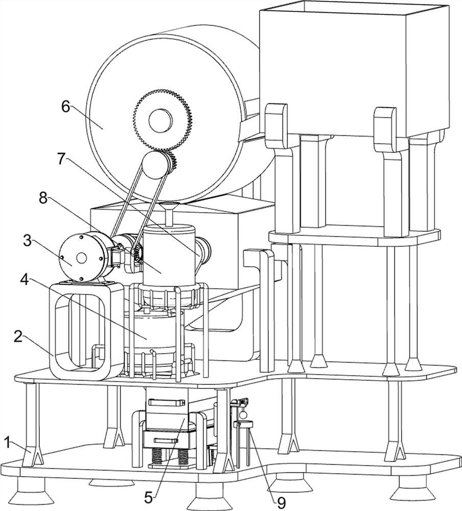
[0058] A syringe crushing device for medical waste recycling, such as Figure 1 to Figure 6 As shown, it includes a base 1, a mounting seat 2, a coarse crushing mechanism 3, a fine crushing mechanism 4, and a material storage mechanism 5. The left front side of the top of the base 1 is connected to the mounting seat 2, and the left rear side of the top of the base 1 is connected to the coarse crushing mechanism 3. A fine crushing mechanism 4 is connected to the front side of the top of the base 1, and a material storage mechanism 5 is provided at the bottom of the base 1.

[0059] The coarse crushing mechanism 3 includes a support bracket 31, a servo motor 32, a first rotating shaft 33, a first pulley assembly 34, a coarse crushing working chamber 35, and a crushing reel 36. A plurality of support brackets 31 are connected to the top left rear side of the base 1, A rough crushing working chamber 35 is connected between the upper parts of the support brackets 31, and two crushi...

Embodiment 2

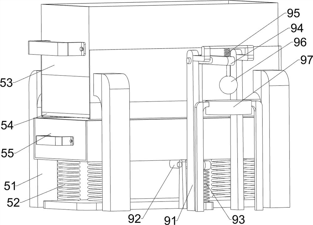
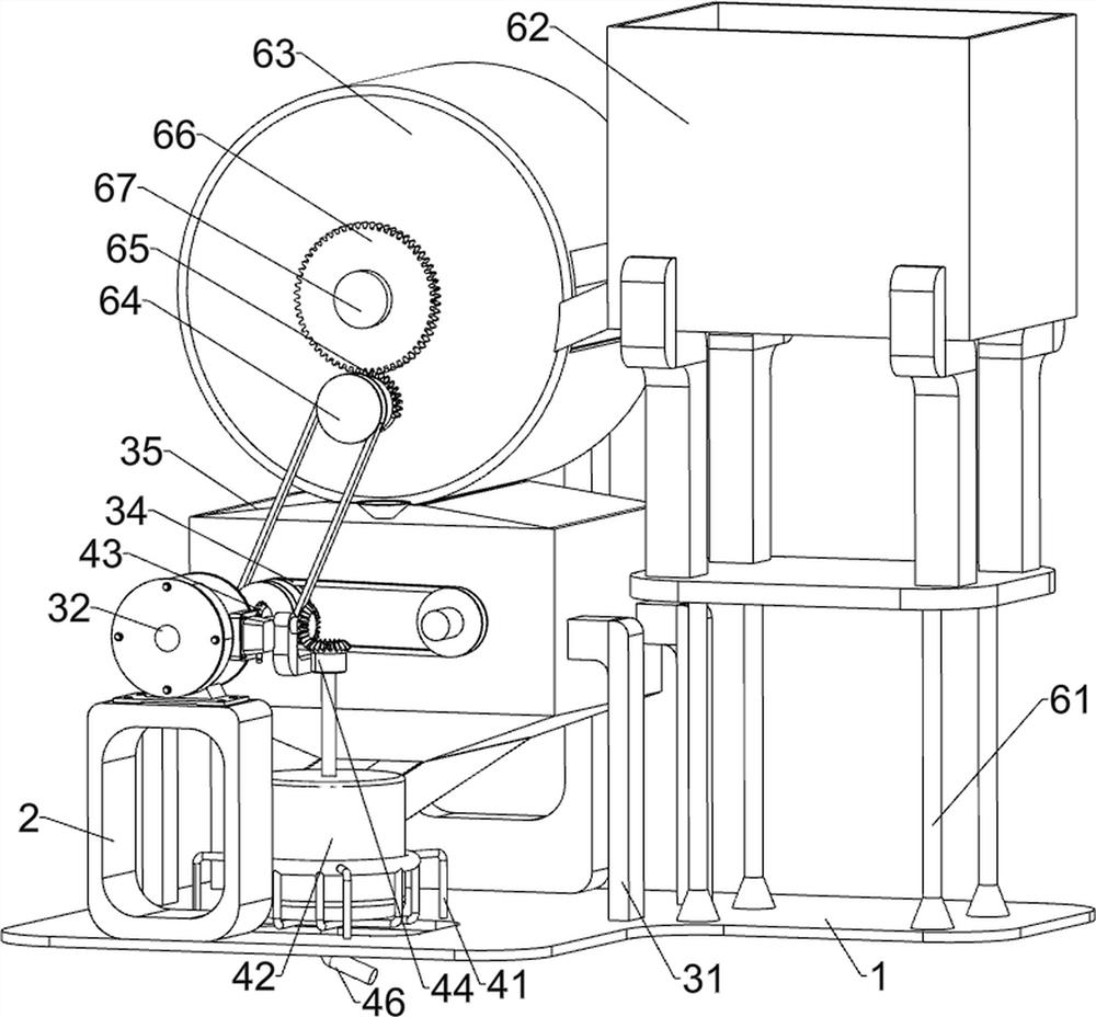
[0064] On the basis of Example 1, such as Figure 1 to Figure 8 As shown, a feeding mechanism 6 is also included, and the feeding mechanism 6 includes a support seat 61, a feeding frame 62, a directional feeding and discharging cylinder 63, a second pulley assembly 64, a sector gear 65, a transmission gear 66, and a second rotating shaft 67 and the quantitative feeding and discharging sheave 68, the right side of the top of the base 1 is connected with a support seat 61, the top of the support seat 61 is connected with a feeding frame 62, the top of the rough crushing working chamber 35 is connected with a directional feeding and discharging cylinder 63, and the directional feeding and discharging cylinder The front side of the cylinder 63 is rotatably connected with a sector gear 65, and a second pulley assembly 64 is connected between the rotating shaft of the sector gear 65 and the first rotating shaft 33, and a second rotating shaft 67 is rotatably connected on the directio...


PUM


Abstract

The invention relates to a crushing device, and particularly relates to an injector crushing device for medical waste recovery. The injector crushing device for medical waste recovery mainly achievesthe effects that automatic intermittent discharging is conducted through a machine, then secondary mincing is conducted, and the mincing quality is guaranteed. The injector crushing device for medicalwaste recovery comprises a base, a rough crushing mechanism, a fine crushing mechanism and a storage mechanism, wherein a mounting seat is connected to one side of the top of the base; the rough crushing mechanism is connected to one side of the top of the base; the fine crushing mechanism is connected to one side of the top of the base; and the storage mechanism is arranged on the lower portionof the base. By arranging the rough crushing mechanism and the fine crushing mechanism, secondary mincing is conducted on an entering injector, and the mincing quality is guaranteed; and by arranginga feeding mechanism, intermittent discharging is conducted on the entering injector by driving a quantitative feeding and discharging groove wheel to rotate, and the situation that the mincing qualityis affected due to the fact that too many injectors are added at a time is prevented.

Description

technical field [0001] The invention relates to a crushing device, in particular to a syringe crushing device for recycling medical waste. Background technique [0002] A syringe is a common medical appliance, consisting of a needle barrel with a small hole at the front end and a matching piston rod. The syringe is used to inject a small amount of liquid or inject it into areas that are inaccessible by other methods or withdraw it from those places. , mainly used for injecting liquid medicine or extracting liquid. Most of the syringes used now are made of plastic, which can be thrown away after one use, which greatly reduces the risk of infection during injection. [0003] The used syringes will be collected centrally. After the collection, the syringes will be placed in the crushing machine, and the fragments will be collected after the crushing. This method puts the syringes in at one time. Too many syringes just put in will easily affect the crushing effect. , if it need...

Claims


Application Information

Patent Timeline
IPC IPC(8): B02C4/08B02C18/10B02C21/00B02C23/00G08B3/02G08B21/24A61L2/18B01D35/02
CPCB02C4/08B02C18/10B02C21/00B02C23/00G08B21/24G08B3/02A61L2/18B01D35/02
Inventor 王付霞
Owner 汕尾市广业环保科技有限公司
Why Eureka
Try Eureka