Cleaning device for hardware tool machining

A technology for hardware tools and cleaning devices, which is applied in the direction of using liquid cleaning methods, cleaning methods and utensils, chemical instruments and methods, etc., can solve the problem that hardware tools cannot be cleaned uniformly, and achieves the effect of being easy to take.

Active Publication Date: 2021-02-19
ZHUZHOU JINGGONG CEMENTED CARBIDE
View PDF13 Cites 1 Cited by
  • Summary
  • Abstract
  • Description
  • Claims
  • Application Information

AI Technical Summary

Problems solved by technology

Due to the different shapes and sizes of the existing hardware tools during cleaning, different hardware tools cannot be cleaned uniformly by a cleaning device

Method used


Image

  • Cleaning device for hardware tool machining
  • Cleaning device for hardware tool machining
  • Cleaning device for hardware tool machining

Examples


Embodiment 1

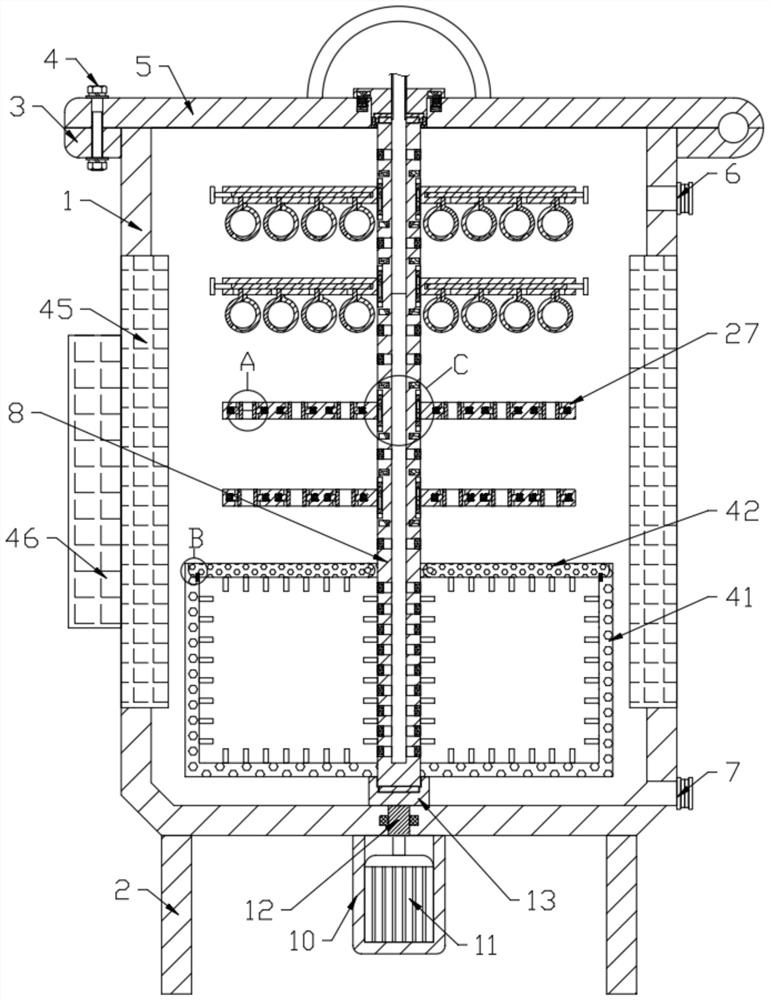
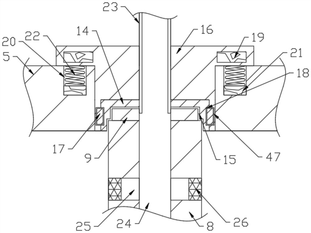
[0027] see Figure 1-7 , a cleaning device for hardware tool processing, comprising a box body 1 and a number of support columns 2 arranged at the lower end of the box body 1, the upper end of the box body 1 is rotatably connected with a cover plate 5, and the upper and lower sides of the side end of the box body 1 are respectively provided with inlets The liquid interface 6 and the liquid outlet interface 7 are connected with the rotating column 8 in the box body 1, and the upper and lower ends of the rotating column 8 are fixedly connected with the cross block 9, and the lower side of the box body 1 is provided with a driving assembly for driving the rotating column 8. The side cross block 9 is engaged with the clamping block 14. The clamping block 14 is provided with a draw-in groove 15 for the clamping of the cross block 9. The clamping block 14 is connected with the moving block 16 in rotation. As for the moving assembly, the box body 1 is provided with a drying assembly,...

Embodiment 2

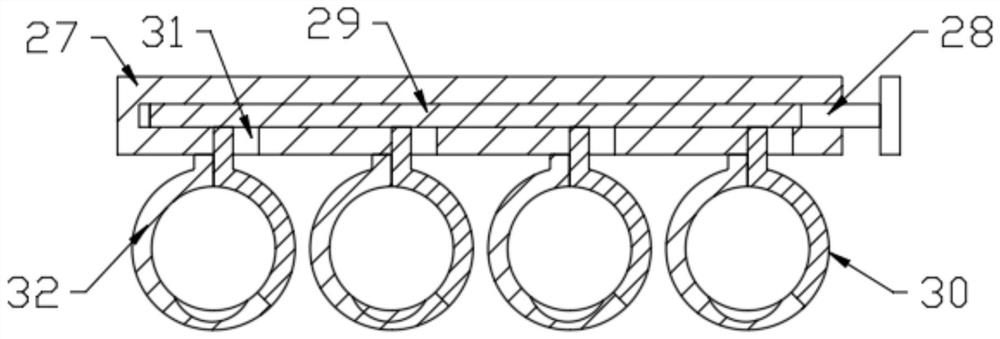
[0045] This embodiment makes further improvements on the basis of Embodiment 1, and the improvements are as follows: a number of ring cylinders 38 fixedly connected to the cross column 27 are slidably connected on the rotating column 8, and the rotating column 8 is provided with ring cylinders 38 for sliding The side groove 39 of the side groove 39, the ring cylinder 38 and the rotating column 8 on both sides of the ring cylinder 38 are respectively provided with the second permanent magnet 40 which is magnetically repulsive. Under the action of the permanent magnet 40, the ring cylinder 38 can be shaken up and down in the side groove 39 on the rotating column 8, and then the horizontal column 27 fixedly connected with the ring cylinder 38 can move up and down while rotating, thereby realizing the clamping on the horizontal column. The tool on the 27 moves up and down while rotating in the cleaning liquid, thereby making the cleaning effect of the tool better.


PUM


Abstract

The invention discloses a cleaning device for hardware tool machining, comprising a box body and a support column. A cover plate is rotatably connected to the upper end of the box body; a liquid inletconnector and a liquid outlet connector are formed in the upper and lower sides of the side end of the box body, respectively; a rotating column, a cross block, a driving assembly, a clamping block,a clamping groove, a moving block, a moving assembly, a drying assembly, a transverse column, a first clamping assembly, a second clamping assembly, a cleaning box and an ultrasonic cleaning assemblyare arranged in the box body; and an energy supply assembly externally connected with a power source is arranged at the side end of the box body. An annular hardware tool is clamped through clamping connection of a movable clamping ring and a fixed clamping ring; a long-strip-shaped tool is inserted into a through hole of the transverse column, and a clamping block clamps the tool under the elastic action of a second spring in a connecting groove in the transverse column; and a special-shaped hardware tool is placed in the cleaning box for cleaning.

Description

technical field [0001] The invention relates to the technical field of cleaning hardware tools, in particular to a cleaning device for processing hardware tools. Background technique [0002] Hardware tools refer to the general term for various metal devices made of iron, steel, aluminum and other metals through forging, rolling, cutting and other physical processing. Hardware tools, divided according to the purpose of the product, can be divided into: tool hardware, construction hardware, daily hardware, locks and abrasives, kitchen and bathroom hardware, household hardware, and hardware parts. When the existing hardware tools are cleaned, the shapes and sizes of the tools are different, so different hardware tools cannot be uniformly cleaned by a cleaning device. Contents of the invention [0003] The object of the present invention is to provide a cleaning device for processing hardware tools to solve the problems raised in the above-mentioned background technology. ...

Claims


Application Information

Patent Timeline
Patent Type & Authority Applications(China)
IPC IPC(8): B08B3/04B08B3/12B08B13/00
CPCB08B3/041B08B3/123B08B13/00Y02P70/10
Inventor 陈明黄朝辉
Owner ZHUZHOU JINGGONG CEMENTED CARBIDE
Why Eureka
Try Eureka