Rapid steel residue cleaning device for sheet metal laser cutting machine

A laser cutting machine and cleaning device technology, applied in laser welding equipment, welding/welding/cutting items, metal processing equipment, etc., can solve the problems of reduced cleaning efficiency, hazards to surrounding staff, and reduced work efficiency, etc., to achieve convenience The effect of using

Active Publication Date: 2021-02-19
德清泰鑫金属制品有限公司
View PDF18 Cites 9 Cited by
  • Summary
  • Abstract
  • Description
  • Claims
  • Application Information

AI Technical Summary

Problems solved by technology

[0004] The purpose of the present invention is to provide a quick cleaning device for iron and steel residues for sheet metal laser cutting machines, in order to solve the problem that the existing cleaning device for cutting machines proposed in the above-mentioned background technology is in use, because the existing cleaning device can only Cleaning in a certain place requires manual cleaning on a regular basis, which reduces work efficiency, and the bristles will raise dust during use, which is not conducive to the health of the staff, thereby reducing the cleaning efficiency and causing physical damage to the surrounding staff. harm problem

Method used


Image

  • Rapid steel residue cleaning device for sheet metal laser cutting machine
  • Rapid steel residue cleaning device for sheet metal laser cutting machine
  • Rapid steel residue cleaning device for sheet metal laser cutting machine

Examples


Embodiment 1

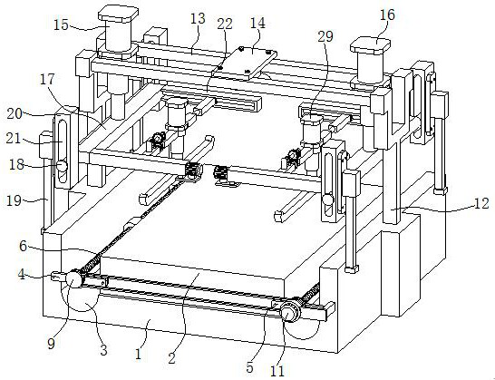
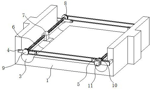
[0027] like Figure 1-5 As shown, the present invention provides a technical solution: a rapid steel residue cleaning device for a sheet metal laser cutting machine, comprising a base 1, a cutting table 2 and a beam 13, the bottom of the cutting table 2 is fixedly connected to the base 1, and the base Both ends of the base 1 are provided with residue collection tanks 3, one end of the front and back of the base 1 is fixedly installed with a first connecting frame 4, and one end of the front and back of the base 1 away from the first connecting frame 4 is fixedly installed with a second connecting frame 4. Frame 5, the opposite sides of two first connecting frames 4 and two second connecting frames 5 are all sleeved with conveying screw 6, and the outside of conveying screw 6 is socketed with cleaning plate 7, two first connecting frames 4 and two The opposite sides of the second connecting frame 5 are all fixedly installed with first limit rods 8, and both sides of one of the ...

Embodiment 2

[0030] like Figure 1-5 As shown, on the basis of Embodiment 1, the present invention provides a technical solution: the cleaning plate 7 is sleeved on the outside of the first limit rod 8, the cleaning plate 7 is located inside the residue collection tank 3, and the cleaning plate 7 and the residue The inner walls of the collecting tank 3 are attached together.

[0031] In this embodiment, by socketing the cleaning plate 7 on the outside of the first limiting rod 8, the first limiting rod 8 will limit the cleaning plate 7, so that the cleaning plate 7 can move normally. Since the cleaning plate 7 and the inner wall of the residue collection tank 3 fit together, the cleaning plate 7 can effectively clean the residue attached to the inner wall of the residue collection tank 3 , thereby facilitating the use of the residue collection tank 3 .

Embodiment 3

[0033] like Figure 1-5 As shown, on the basis of Embodiment 1 and Embodiment 2, the present invention provides a technical solution: there are two crossbeams 13, and both sides of the crossbeam 13 are fixedly equipped with mounting frames 12, and the bottom of the mounting frame 12 is connected to the base 1 fixed connection.

[0034] In this embodiment, the crossbeam 13 is supported by setting the mounting frame 12 , and the crossbeam 13 is connected to the base 1 through the mounting frame 12 , which is beneficial to the stable support of the crossbeam 13 .


PUM


Abstract

The invention discloses a rapid steel residue cleaning device for a sheet metal laser cutting machine. The rapid steel residue cleaning device comprises a base, a cutting table and cross beams, wherein a cleaning plate sleeves a conveying screw; a first lifting air cylinder is fixedly installed at one ends of the tops of the cross beams, and a second lifting air cylinder is fixedly installed at one ends, away from the first lifting air cylinder, of the tops of the cross beams; two frames are fixedly installed at one side of each receiving plate; sliding plates sleeve adjusting screws and second limiting rods respectively; a transmission rod sleeves the opposite sides of two sliding plates; a telescopic air cylinder is fixedly installed at the top of each support plate; and a scraping plateis fixedly installed at the bottom of each telescopic air cylinder. Through the arrangement of the first lifting air cylinder, the second lifting air cylinder and the telescopic air cylinders, the scraping plates can be moved to the top of the cutting table and move left and right under the action of the second limiting rods, the adjusting screws and adjusting motors, and the two scraping platesoperate at the same time, so that steel residues generated by the sheet metal laser cutting machine at the top of the cutting table can be cleaned and the rapid cleaning effect is achieved.

Description

technical field [0001] The invention belongs to the technical field of cutting machines, and in particular relates to a device for quickly cleaning iron and steel residues for sheet metal laser cutting machines. Background technique [0002] Cutting machine is divided into flame cutting machine, plasma cutting machine, laser cutting machine, water cutting and so on. The laser cutting machine has the fastest efficiency, the highest cutting precision, and the cutting thickness is generally small. The cutting speed of the plasma cutting machine is also very fast, and the cutting surface has a certain slope. The flame cutting machine is aimed at thicker carbon steel materials. With the development of the modern mechanical processing industry, the requirements for cutting quality and precision are constantly improving, and the requirements for improving production efficiency, reducing production costs, and highly intelligent automatic cutting functions are also increasing. The...

Claims


Application Information

Patent Timeline
Patent Type & Authority Applications(China)
IPC IPC(8): B23K26/16B23K26/38
CPCB23K26/16B23K26/38B23K2103/04Y02P70/10
Inventor 陈家窕包松富陈景新翁士扬吕存昌郑成武
Owner 德清泰鑫金属制品有限公司
Why Eureka
Try Eureka