An automatic feeding device for shell sheets for intelligent manufacturing

A technology of automatic feeding and intelligent manufacturing, which is applied in the direction of manufacturing tools, metal processing equipment, metal processing, etc., and can solve problems such as difficulty in ensuring the quality of the shell and uneven application of force

Active Publication Date: 2021-12-03
金镁智高科技(广东)有限公司
View PDF8 Cites 0 Cited by
  • Summary
  • Abstract
  • Description
  • Claims
  • Application Information

AI Technical Summary

Problems solved by technology

[0004] In order to overcome the disadvantages of the prior art that the casings are uniformly conveyed, relying on manual sequential engagement, uneven application of force, and difficulty in ensuring the quality of the casings, the purpose of the present invention is to provide a separate transmission of the casings, which drives the machine to It is sequentially engaged to ensure the quality of the intelligent manufacturing shell sheet automatic feeding device

Method used


Image

  • An automatic feeding device for shell sheets for intelligent manufacturing
  • An automatic feeding device for shell sheets for intelligent manufacturing
  • An automatic feeding device for shell sheets for intelligent manufacturing

Examples


Embodiment 1

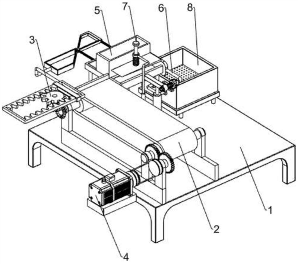
[0058] An automatic feeding device for shell sheets for intelligent manufacturing, such as Figure 1 to Figure 4 As shown, it includes a mounting seat 1, a feeding mechanism 2, a striking mechanism 3 and a driving mechanism 4. 2. The right front side is connected with a driving mechanism 4.

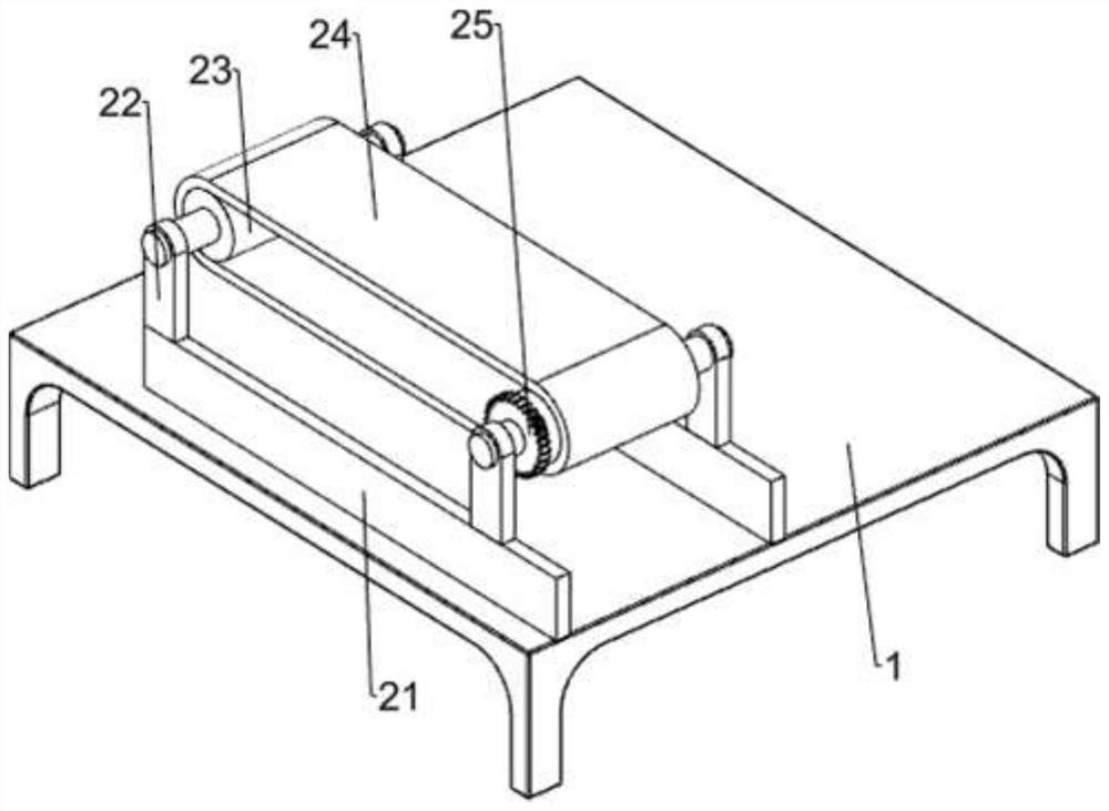
[0059] The feeding mechanism 2 includes a horizontal plate 21, a first mounting plate 22, a roller 23, a conveyor belt 24, and a first full-toothed gear 25. The first mounting plate 22 is arranged, and the first mounting plate 22 on the vertical same side is connected with rollers 23 in rotation, and the conveyor belt 24 is connected between the rollers 23, and the front side of the transmission shaft of the right roller 23 is connected with the first full body. toothed gear 25 .

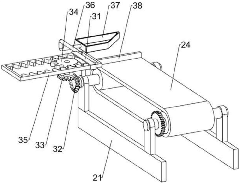
[0060]The striking mechanism 3 includes a first sliding sleeve 31, a first bevel gear 32, a second bevel gear 33, a missing gear 34, a rack frame 35, a first connecting rod 36, a first wedge block 37 and a bl...

Embodiment 2

[0064] On the basis of Example 1, such as Figure 5 to Figure 8 As shown, a blanking mechanism 5 is also included, and the blanking mechanism 5 includes a first mounting column 51, a placement plate 52, a blanking frame 54, a push plate 55, a second wedge block 56 and a first spring 57, and the mounting seat 1 There are four first installation columns 51 on the left rear side of the top, the top of the first installation column 51 is connected with a placement plate 52, the top of the placement plate 52 is provided with a through hole 53, and the middle side of the top of the placement plate 52 is connected with a blanking frame 54. The left side of the plate 52 is slidably connected with a push plate 55, the push plate 55 is slidably connected with the inner wall of the through hole 53, the left side of the push plate 55 is connected with a second wedge 56, and the second wedge 56 cooperates with the first wedge 37, Two first springs 57 are connected between the right side of...


PUM


Abstract

The invention relates to an automatic feeding device, in particular to an automatic feeding device for shell sheets for intelligent manufacturing. The main purpose is to provide an automatic feeding device for shell sheets for intelligent manufacturing, which transmits the shell separately, drives the machine to engage it in sequence, and ensures the quality of the shell. An automatic feeding device for shell sheets for intelligent manufacturing, comprising: a mounting seat, a feeding mechanism is connected to one side of the top of the mounting seat; a striking mechanism, a striking mechanism is connected to one side of the feeding mechanism; a driving mechanism, the feeding mechanism A drive mechanism is connected to one side. Through the cooperation of the driving mechanism and the feeding mechanism, the upper casing on the conveyor belt is driven to move to the left to match the feeding; through the cooperation of the feeding mechanism and the striking mechanism, the rack frame can move backwards to push the upper casing to move backwards. To achieve the effect of automatic feeding.

Description

technical field [0001] The invention relates to an automatic feeding device, in particular to an automatic feeding device for shell plates used in intelligent manufacturing. Background technique [0002] The shell is a flaky structure surrounded by two curved surfaces, the inner and the outer. It mainly resists the external load with the mid-plane stress uniformly distributed along the thickness. This internal force feature of the shell makes it more fully utilize the material strength than the flat plate. , has a greater carrying capacity, so that the guaranteed product can prolong the life and play an important role. [0003] In the prior art, the shells are uniformly conveyed, relying on the staff on both sides of the workbench to engage them sequentially, which is inefficient, and it is difficult to ensure the quality of the shells by squeezing and engaging manually. Contents of the invention [0004] In order to overcome the disadvantages of the prior art that the ca...

Claims


Application Information

Patent Timeline
Patent Type & Authority Patents(China)
IPC IPC(8): B23P19/00
CPCB23P19/001
Inventor 黄伍香
Owner 金镁智高科技(广东)有限公司
Why Eureka
Try Eureka