
Multifunctional industrial mechanical arm and using method thereof

An industrial machinery, multi-functional technology, applied in manipulators, program-controlled manipulators, manufacturing tools, etc., can solve problems such as unfavorable production adjustment, small operating range, and reduced production efficiency, so as to reduce labor costs, increase operating range, improve The effect of work efficiency

Inactive Publication Date: 2021-02-19
合肥酷显智能科技有限公司
View PDF0 Cites 3 Cited by
  • Summary
  • Abstract
  • Description
  • Claims
  • Application Information

AI Technical Summary

Problems solved by technology

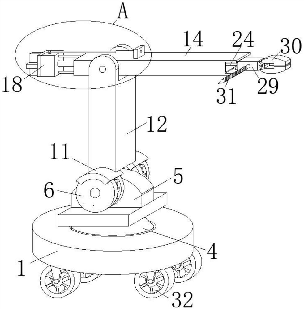
[0004] The purpose of the present invention is to provide a multi-functional industrial robot arm and its use method to solve the problem that the general industrial robot arm proposed in the above background technology can only simply perform grabbing work, has a single function and a simple structure, and cannot adapt to modern industrial production. The multi-faceted requirements limit the application range of industrial robotic arms and reduce production efficiency. Moreover, the operating range of general industrial robotic arms is small, and it is impossible to precisely process any point on the three-dimensional space, which makes the work efficiency low and increases labor. cost, which brings problems that are not conducive to production adjustment

Method used


Image

  • Multifunctional industrial mechanical arm and using method thereof
  • Multifunctional industrial mechanical arm and using method thereof
  • Multifunctional industrial mechanical arm and using method thereof

Examples


Embodiment Construction

[0026] The technical solutions in the embodiments of the present invention will be clearly and completely described below in conjunction with the embodiments of the present invention. Apparently, the described embodiments are only some of the embodiments of the present invention, not all of them. Based on the embodiments of the present invention, all other embodiments obtained by persons of ordinary skill in the art without creative efforts fall within the protection scope of the present invention.

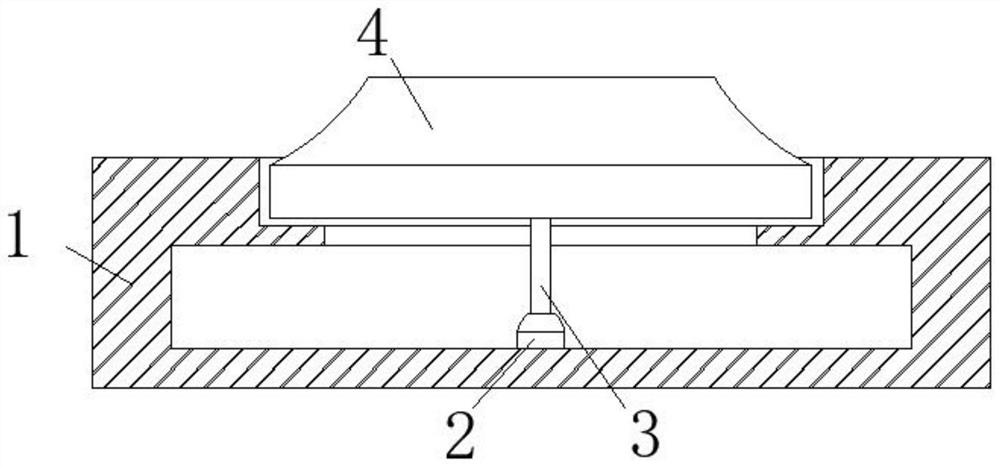
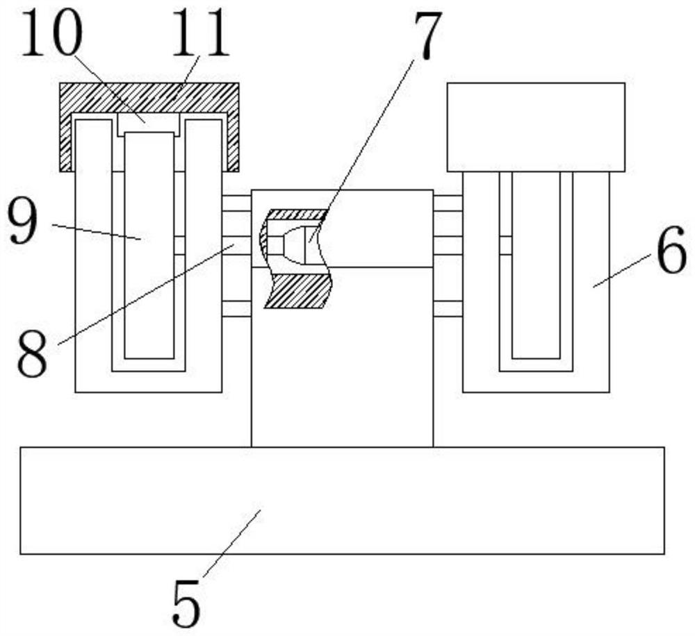
[0027] Such as Figure 1-7As shown, a multifunctional industrial mechanical arm includes a base 1, a groove 1 and a cavity 1 are respectively provided on the top surface and the side wall of the base 1, a motor 2 is installed on the bottom surface of the cavity 1, and the output end of the motor 2 A transmission shaft 3 is fixedly connected to the top, and the other end of the transmission shaft 3 extends into the groove 1, and a turntable 4 is fixedly connected to the input end o...


PUM


Abstract

The invention discloses a multifunctional industrial mechanical arm and a using method thereof. The multifunctional industrial mechanical arm comprises a base, a first groove and a first cavity are formed in the top face and the side wall of the base correspondingly, a motor is installed on the bottom face of the first cavity, a first transmission shaft is fixedly connected to the output end of the motor, the other end of the first transmission shaft extends into the first groove, a rotating disc is fixedly connected to the input end of the first transmission shaft, the rotating disc is rotatably connected with the first groove in a sleeving mode, a connecting block is fixedly connected to the top surface of the rotating disc, a second cavity is formed in the side wall of the connecting block, and a shell is fixedly connected to the side wall of the connecting block. The operation range of the industrial mechanical arm can be enlarged, meanwhile, any point in a three-dimensional spacecan be accurately machined, the working efficiency is improved, production adjustment is facilitated, the use function of the mechanical arm can be replaced, the mechanical arm is diversified in function, the multi-aspect requirements of modern industrial production can be met conveniently, and the production efficiency is improved.

Description

technical field [0001] The invention belongs to the field of industrial production equipment, in particular to a multifunctional industrial mechanical arm and a method for using the same. Background technique [0002] The robotic arm is the most widely used automatic mechanical device in the field of robotics. It can be seen in the fields of industrial manufacturing, medical treatment, entertainment services, military, semiconductor manufacturing, and space exploration, although their shapes are different. They are different, but they all have a common feature, that is, they can accept instructions and precisely locate to a certain point in three-dimensional space for operation. [0003] The general industrial robotic arms on the market can only perform grasping work simply, with a single function and a simple structure, which cannot meet the various needs of modern industrial production, which limits the application range of industrial robotic arms and reduces production ef...

Claims


Application Information

Patent Timeline
Patent Type & Authority Applications(China)
IPC IPC(8): B25J5/00B25J9/04B25J9/12B25J11/00
CPCB25J5/007B25J9/04B25J9/12B25J11/005
Inventor 童亮
Owner 合肥酷显智能科技有限公司
Learn More