Wing connecting structure of sensor unmanned aerial vehicle, wing and unmanned aerial vehicle

A technology for connecting structure and unmanned aerial vehicle, applied in the field of unmanned aerial vehicle, can solve the problems of difficult mechanical connection method and thick foam interlayer, and achieve the effect of satisfying the structural integrity of the wing, the satisfactory connection strength, and the feasible connection process

Active Publication Date: 2021-02-19
AEROSPACE CH UAV CO LTD
View PDF14 Cites 0 Cited by
  • Summary
  • Abstract
  • Description
  • Claims
  • Application Information

AI Technical Summary

Problems solved by technology

In addition, the foam interlayer of the integrated skin is relatively th

Method used


Image

  • Wing connecting structure of sensor unmanned aerial vehicle, wing and unmanned aerial vehicle
  • Wing connecting structure of sensor unmanned aerial vehicle, wing and unmanned aerial vehicle
  • Wing connecting structure of sensor unmanned aerial vehicle, wing and unmanned aerial vehicle

Examples


Embodiment

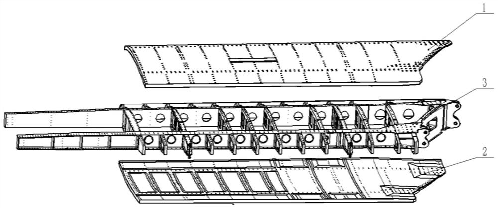
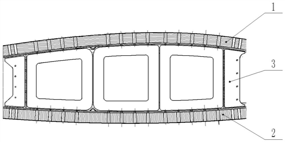
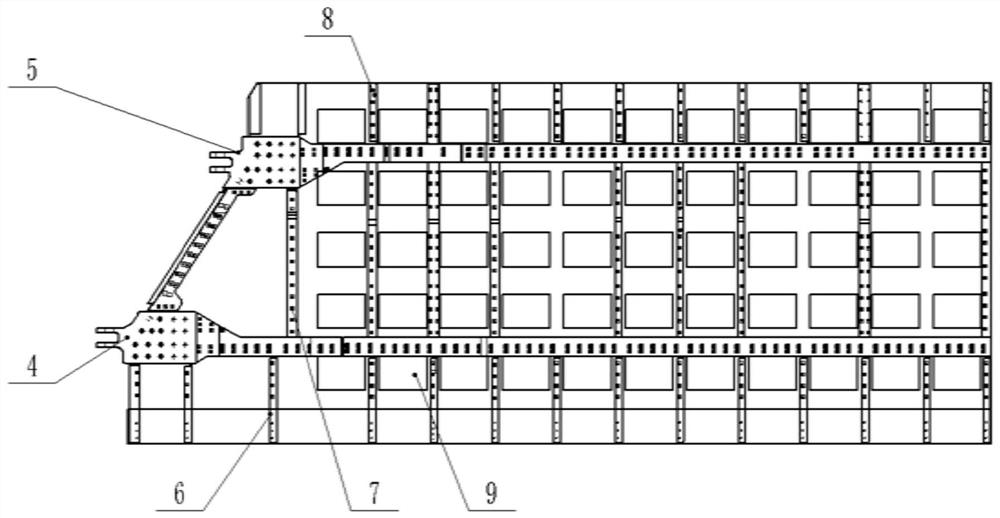
[0072] figure 1 An exploded view of the structure of the wing of the drone of the present embodiment is shown; figure 2 A sectional view of the wing of the drone of the present embodiment is shown; image 3 A top view of the drone wing of the present embodiment is shown; Figure 4 A schematic diagram of the wing connection structure of this embodiment is shown.

[0073] Such as figure 1 As shown, the UAV wing includes a wing skeleton 3 and an upper skin 1 and a lower skin 2, such as figure 2 As shown, the upper skin 1 and the lower skin 2 cover the wing frame 3; wherein, the upper skin 1 and the lower skin 2 have the same structure, as Figure 4 As shown, it includes a main bearing plate 12 of carbon fiber plate material, a foam plate 11 and a glass fiber plate 10 stacked in sequence from the inside to the outside, and the antenna unit 9 is built in the foam plate 11;

[0074] Such as image 3 As shown, the edge of the wing frame 3 includes a front beam 4 arranged alon...


PUM


Abstract

The invention discloses a wing connecting structure of a sensor unmanned aerial vehicle, a wing and an unmanned aerial vehicle. The connecting structure comprises a plurality of stepped holes, a plurality of connecting holes, a plurality of connecting pieces and a plurality of plugging elements. The multiple stepped holes are distributed in the skin in the edge strip direction of a wing frameworkand keep away from an antenna unit, the large-diameter ends of the stepped holes sequentially penetrate through a glass fiber plate and a foam plate, and the small-diameter ends of the stepped holes penetrate through a main force bearing plate; the plurality of connecting holes are distributed in the edge strip of the wing framework and are in one-to-one correspondence with the stepped holes; eachconnecting piece is used for fixing the main force bearing plate of the skin on the wing framework through one stepped hole and one connecting hole; and each plugging element is put in one stepped hole, so that the surface of the skin is complete. On the premise of ensuring that the antenna assembly in the wing can work normally, the requirement for structural integrity of a wing is met, the skinand framework connecting process is feasible, and the connecting strength meets the requirement.

Description


Claims


Application Information

Patent Timeline
Owner AEROSPACE CH UAV CO LTD
Why Eureka
Try Eureka